
Control method and system based on train group

A control method and group technology, applied in the direction of the control system of the transportation center, automatic system, railway car body parts, etc., can solve the problem of small stations occupying the throat area or even the section, the driver's work intensity is high, and the probability of rail breakage is increased, etc. problems, to achieve the effect of improving the occupancy capacity of the throat area, shortening the driving interval, and increasing the driving density

Active Publication Date: 2021-11-26
CRSC RESEARCH & DESIGN INSTITUTE GROUP CO LTD
View PDF4 Cites 5 Cited by
  • Summary
  • Abstract
  • Description
  • Claims
  • Application Information

AI Technical Summary

Problems solved by technology

[0004] If the axle load is too large, the load-carrying requirements of infrastructure such as bridges, culverts, and roadbeds are high, and a large amount of investment is required for reinforcement, and the renovation period is long, which will affect normal transportation operations; Expansion and reconstruction will increase the land area; the marshalling and unmarshalling of heavy-duty combined trains will occupy station resources for a long time, and small stations will also occupy the throat area or even the interval, seriously affecting on-site transportation operations
The length and weight of the train increase, which makes it difficult to solve the problem of longitudinal force in the operation of the train, which is likely to cause off-line accidents; the overweight of the vehicle accelerates the fatigue of the rails and increases the probability of rail breakage; It is very difficult to rescue when a problem occurs; the driver of the combined train has a high workload and requires a high level of control consistency
There is no system and control method for controlling group trains in the prior art

Method used


Image

  • Control method and system based on train group
  • Control method and system based on train group
  • Control method and system based on train group

Examples


Embodiment Construction

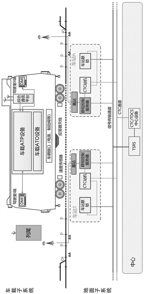
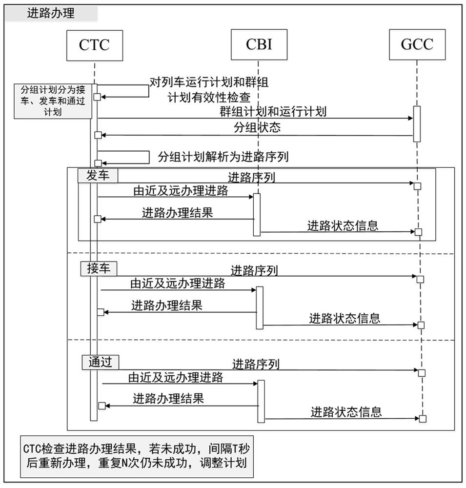
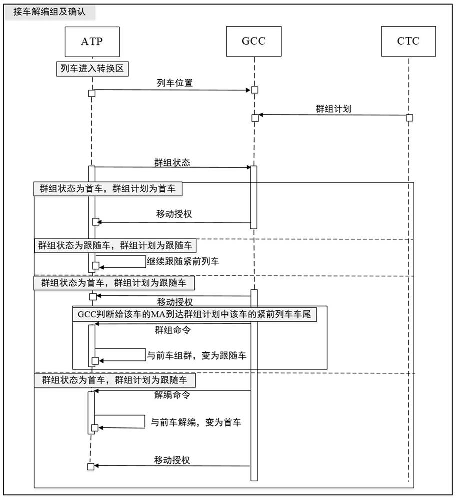
[0069] In order to make the purpose, technical solutions and advantages of the embodiments of the present invention more clear, the technical solutions in the embodiments of the present invention will be clearly and completely described below in conjunction with the accompanying drawings in the embodiments of the present invention. Obviously, the described embodiments It is a part of embodiments of the present invention, but not all embodiments. Based on the embodiments of the present invention, all other embodiments obtained by persons of ordinary skill in the art without making creative efforts belong to the protection scope of the present invention.

[0070] The train group control system in the embodiment of the present invention controls the trains according to the train groups, coordinates the trains as a whole, and then obtains the optimization of the group. Therefore, under the premise of not increasing the axle load and the length of the train, only through the change...


PUM


Abstract

The invention provides a control method and a system based on a train group. According to the control method and system based on the train group, the train adopts a group control mode, the running interval is further shortened, the running density is improved, and the MB-VG control method based on relative real-time speed, continuous space distance and group self-adaptive adjustment fusion is provided. An absolute time-relative speed-dynamic position model is constructed to realize a train group control system. According to the system, the trains are controlled according to train groups, all the trains are comprehensively coordinated, and then group optimization is obtained. Therefore, on the premise of not increasing the axle weight and the train length, the running density is greatly improved and the maximum transport capacity is obtained only by changing a train control system. According to the train group control method, time and space are more subdivided, the tracking interval is better shortened, and the tracking density is improved; meanwhile, group control is considered, and collective benefits can be better achieved through cooperative control.

Description

technical field [0001] The invention belongs to the field of train control, in particular to a control method and system based on train groups. Background technique [0002] The existing railway train operation control method is a one-dimensional control method based on space units and with the concept of blockage as the core, which lasts for more than one hundred years. It performs independent space control on a single train. The national railway train control system CTCS-2 (Chinese Train Control System, China Train Operation Control System) and CTCS-3, subway train control system CBTC (Communication Based Train Control System, communication-based automatic train control system), and foreign railway train control systems such as ETCS (European Train Control System, European train control system), etc., the train operation control system is constructed with a single train as the control object. Under this framework, the existing railway transport capacity is close to the th...

Claims


Application Information

Patent Timeline
Patent Type & Authority Applications(China)
IPC IPC(8): B61L27/04B61L27/00
CPCB61L27/04
Inventor 徐宗奇姚文华于晓泉李蔚张万强张文汇刘鸿飞蔡菁华岳朝鹏刘长波周宇晖
Owner CRSC RESEARCH & DESIGN INSTITUTE GROUP CO LTD
Learn More