
Docking station with camera

A camera and docking station technology, applied in the field of docking stations with cameras, can solve the problems of increasing the surface area, damage to the connected equipment, data cable data cable entanglement, etc., so as to reduce the plane space, improve the service life, and improve the applicability effect.

Inactive Publication Date: 2021-11-26
黎琴
View PDF0 Cites 1 Cited by
  • Summary
  • Abstract
  • Description
  • Claims
  • Application Information

AI Technical Summary

Problems solved by technology

[0003] 1. Both the docking station and the camera need to be placed on the table, which increases the area occupied by the table when it is used, and the data cable on the docking station is also easily entangled with the data cable on the camera
[0004] 2. The length of the data cable of the existing docking station and the camera is fixed, and the connection port in the docking station cannot be extended outwards. In some specific use environments, external devices are likely to be unable to communicate with the docking station due to the long distance. connection, reducing the suitability of the docking station
[0005] 3. When the connection port on the docking station is not in use, it is easy to get dust inside because it is not protected, causing the dust to easily block the connection port of the docking station, and also affects the sensitivity of the connection port, thereby reducing the docking station. service life
[0006] 4. The existing docking station is usually placed directly on the table when used. When water or beverages are spilled on the table, it is easy to flow into the docking station. As a result, the ordinary docking station without a base is likely to cause damage to the docking station and the docking station due to water ingress. Damage to its externally connected equipment

Method used


Image

  • Docking station with camera
  • Docking station with camera
  • Docking station with camera

Examples


Embodiment Construction

[0031] In order to make the technical means, creative features, goals and effects achieved by the present invention easy to understand, the present invention will be further described below in conjunction with specific illustrations. It should be noted that, in the case of no conflict, the embodiments in the present application and the features in the embodiments can be combined with each other.

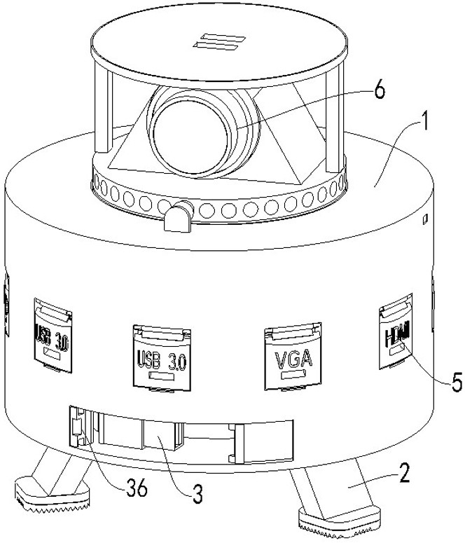
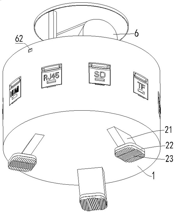
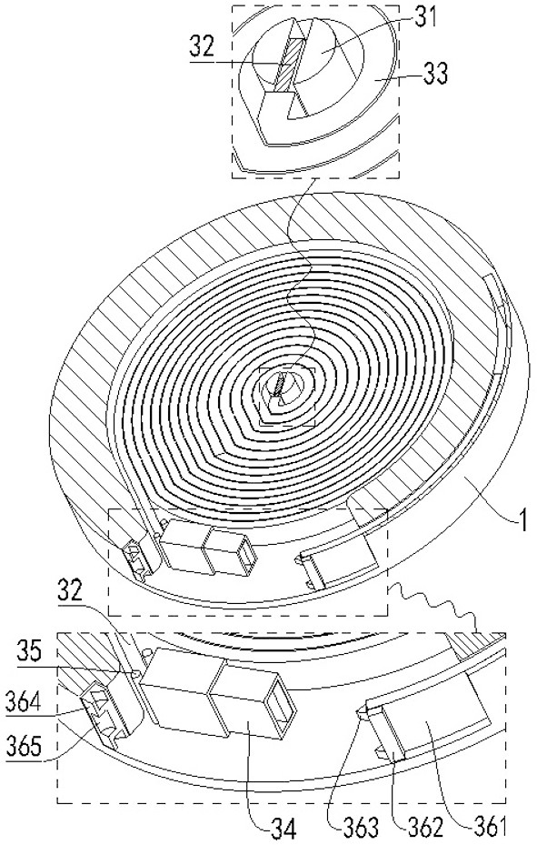
[0032] refer to figure 1 and Figure 4 , a docking station with a camera, including a cylindrical shell 1, a support unit 2, a connecting unit 3, a control board 4, an interface unit 5 and a camera unit 6, the cylindrical shell 1 is a cylindrical structure with an upper end open , a support unit 2 is provided on the lower end surface of the cylindrical shell 1, and an installation groove and a control groove are sequentially opened between the lower end surface and the lower side wall of the cylindrical shell 1 from bottom to top, and a connection unit 3 is arranged in the installat...


PUM


Abstract

The present invention relates to a docking station with a camera. The docking station comprises a cylindrical shell, a supporting unit, a connecting unit, a control panel, an interface unit and a camera shooting unit, the cylindrical shell is of a cylindrical structure with an opening in the upper end, the supporting unit is arranged on the lower end face of the cylindrical shell, and a mounting groove and a control groove are sequentially formed between the lower end face and the lower side wall of the cylindrical shell from bottom to top; and a connecting unit is arranged in the mounting groove, a control panel is arranged in the control groove, an interface unit is arranged on the outer side face of the cylindrical shell, and a camera unit is arranged in the upper end of the cylindrical shell. The method can solve the problems that in the process that a docking station and a camera are used by a desktop computer at the same time, the plane space, occupied by the camera and the docking station, on a table top is large; external equipment cannot be connected with the docking station due to the fact that the distance between the external equipment and the docking station is long; dust is easy to enter the connecting port when the connecting port is not used; and when water or beverage is spilled on the table top, the water or the beverage easily flows into the docking station without a base, and the like.

Description

technical field [0001] The invention relates to the field of docking stations, in particular to a docking station with a camera. Background technique [0002] A docking station, also known as a port replicator, is an external device for a computer. By duplicating or even extending the ports of the computer, the computer can be connected to multiple accessories or external devices (such as power adapters, network cables, mice, external keyboards, printers, and external monitors) at the same time. Existing ordinary docking stations are usually designed for notebook computers. Because notebook computers basically have camera functions, existing ordinary docking stations usually do not have camera functions. However, ordinary desktop computers need to have camera functions while using docking stations. In this case, both a docking station and a camera need to be connected, so there are usually the following problems in the process of using a docking station and a camera at the ...

Claims


Application Information

Patent Timeline
Patent Type & Authority Applications(China)
IPC IPC(8): G06F13/38
CPCG06F13/382
Inventor 黎琴
Owner 黎琴
Learn More