Conductive circuit drawing equipment

A technology of conductive lines and equipment, applied in the field of conductive line drawing equipment

Inactive Publication Date: 2021-11-30
深圳市微特芯科技有限公司
View PDF0 Cites 0 Cited by
  • Summary
  • Abstract
  • Description
  • Claims
  • Application Information

AI Technical Summary

Problems solved by technology

[0005] The object of the present invention is to provide a conductive line drawing device to solve the problems of the prior art shortcomings in the above-mentioned background technology

Method used


Image

  • Conductive circuit drawing equipment
  • Conductive circuit drawing equipment
  • Conductive circuit drawing equipment

Examples


Embodiment Construction

[0034] The following will clearly and completely describe the technical solutions in the embodiments of the present invention with reference to the accompanying drawings in the embodiments of the present invention. Obviously, the described embodiments are only some, not all, embodiments of the present invention. Based on the embodiments of the present invention, all other embodiments obtained by persons of ordinary skill in the art without creative efforts fall within the protection scope of the present invention.

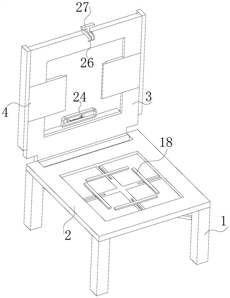
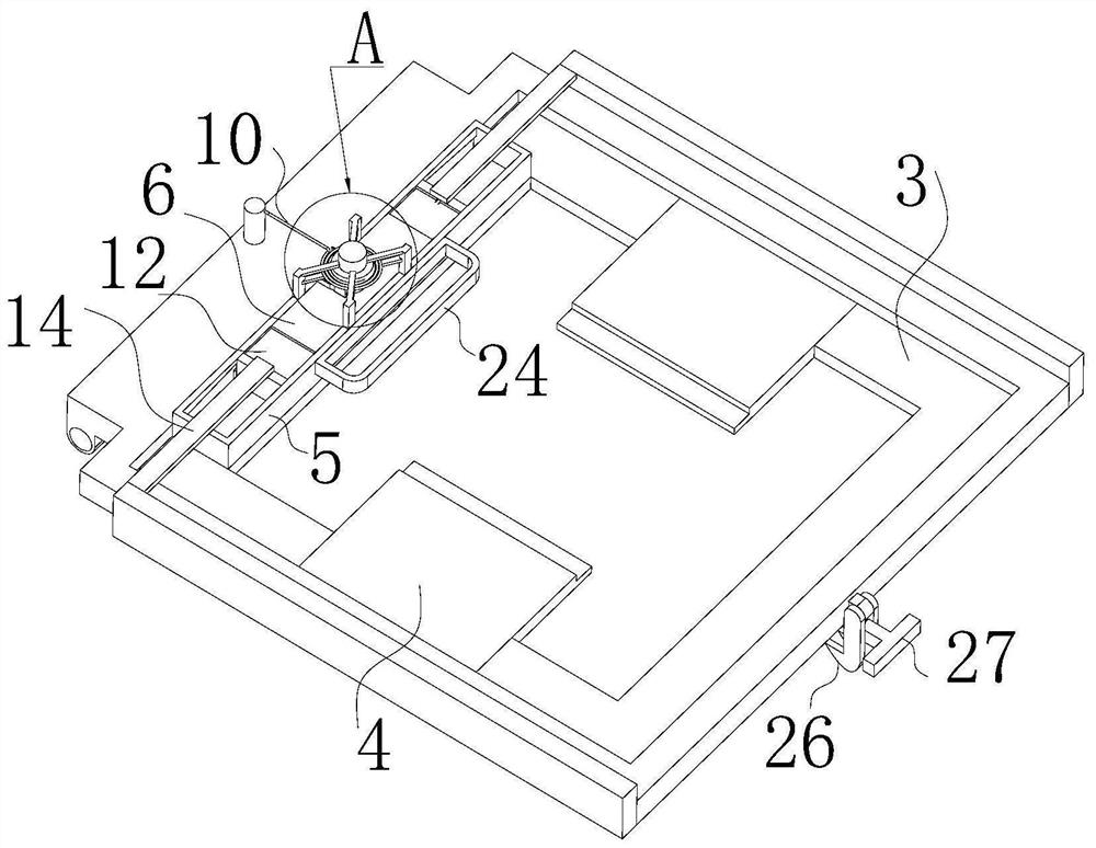
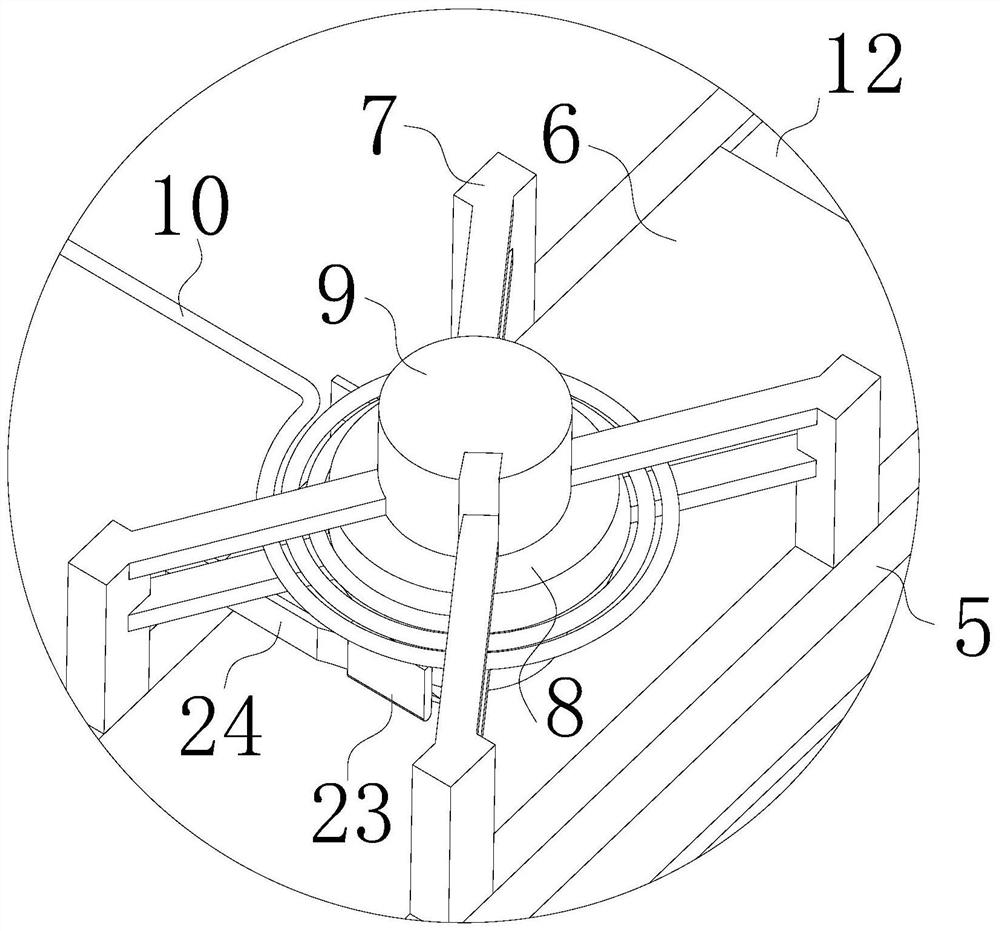
[0035] see Figure 1-10 , the present invention provides a technical solution: a conductive circuit drawing device, including a support frame 1, a supporting plate 2 is fixedly connected to the supporting frame 1, a pressing plate 3 is rotatably connected to the supporting plate 2, and a pressing plate 3 is arranged There is a measuring mechanism for measuring the width of the printing plate, and a printing mechanism for printing is slidably connected to the pressi...


PUM


Abstract

The invention discloses conductive circuit drawing equipment in the field of circuit board manufacturing. A supporting frame is fixedly connected with a bearing plate, the bearing plate is rotatably connected with a pressing plate, the pressing plate is provided with a measuring mechanism for measuring the width of a printing plate, and the pressing plate is slidably connected with a printing mechanism for printing. According to the conductive circuit drawing equipment, the printing plate is installed to drive two first clamping plates to move towards the two sides, in the process, the first clamping plates can drive first sliding plates fixedly connected with the first clamping plates to move synchronously, and the width of a discharging opening of a storage box is consistent with the width of the installed printing plate, so that it is guaranteed that soldering tin in the storage box cannot leak in the printing process, lines on the printing plate cannot be completely covered, and the problem of waste of filling soldering tin in the prior art is solved.

Description

technical field [0001] The invention relates to the field of circuit board manufacturing, in particular to a conductive circuit drawing device. Background technique [0002] In the prior art, the production of circuit board samples is limited by the cost. Usually, equipment for mass production is not used for production, and small devices are generally used for production. In the process of making circuit boards, circuit boards need to pass through metal materials. In terms of each line is filled, so that the circuit board can conduct electricity. [0003] However, the existing technology center usually adopts artificial methods for filling the circuit board with conductive metal, by covering the printed board on the circuit board, then pouring the solder on the printed board, and then scraping the solder into the circuit board by the scraper, however this During operation, the scraper will cause the solder to escape everywhere, which will lead to the waste of solder, and i...

Claims


Application Information

Patent Timeline
Patent Type & Authority Applications(China)
IPC IPC(8): B41F1/04B41F1/40B41F1/26H05K3/12
CPCB41F1/04B41F1/40B41F1/26H05K3/12B41P2217/10B41P2217/50
Inventor 李海洋
Owner 深圳市微特芯科技有限公司
Why Eureka
Try Eureka