Device and method for testing shield tunnel excavation face stability under gushing condition

A technology of stability test and shield tunnel, which is applied in soil material testing, material inspection products, etc., can solve the problem of unsystematic research on the stability of shield excavation surface, achieve significant scientific research value and engineering value, enrich soil and water effect of load

Pending Publication Date: 2021-11-30
GUANGXI UNIV
View PDF0 Cites 0 Cited by
  • Summary
  • Abstract
  • Description
  • Claims
  • Application Information

AI Technical Summary

Problems solved by technology

[0003] At present, most studies on the stability of the excavation face of shield tunneling are based on dry soil test conditions or static water conditions, and there is no systematic study on the stability of the excavation face of shield tunneling under spring conditions.

Method used


Image

  • Device and method for testing shield tunnel excavation face stability under gushing condition
  • Device and method for testing shield tunnel excavation face stability under gushing condition
  • Device and method for testing shield tunnel excavation face stability under gushing condition

Examples


Embodiment 1

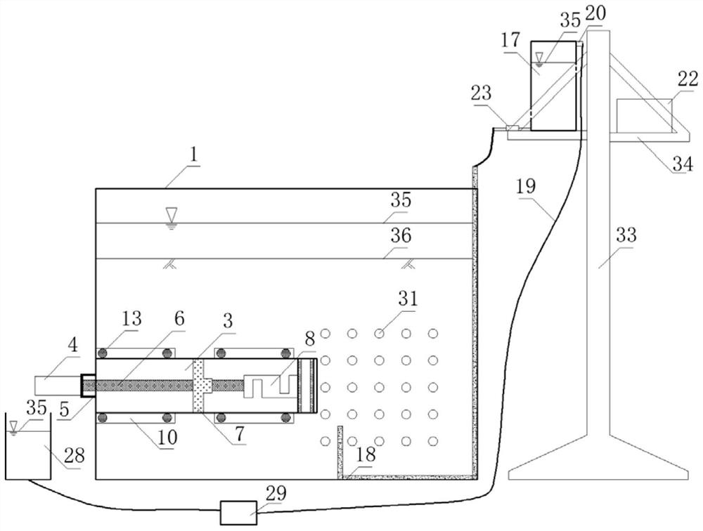
[0043] Such as figure 1 As shown, the shield tunnel excavation surface stability test device under spring conditions according to the present invention includes a model box 1, a tunnel excavation surface module, a water circulation module and a data acquisition module.

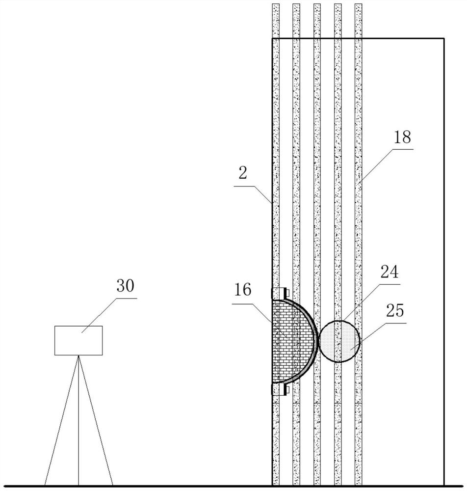
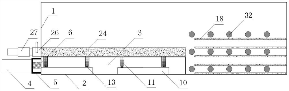
[0044] Such as figure 2 , image 3 As shown, the model box 1 is a cube, and the tunnel model 3 is connected to the measuring panel by bolts 13. The observation panel of the model box 1 is a toughened glass plate 2 with a thickness not less than 6 mm, and the side walls and bottom plates are all stainless steel with a thickness not less than 10 mm. plate.

[0045] The tunnel excavation surface module includes a tunnel model 3 , a servo motor 4 , a steel support 5 , a transmission rod 6 , a linear bearing 7 , a tension and pressure sensor 8 and an excavation panel 9 . The tunnel model 3 is a stainless steel semicircle-arc steel pipe, the wall thickness of the stainless steel semicircle-arc steel pipe is 12mm...

Embodiment 2

[0049] Such as Figure 8 As shown, the shield tunnel excavation face stability test method under the gushing condition of the present invention comprises the following steps:

[0050] (1) Clean up the site: fix the device on a clean and level site, install and clean the test device according to the fixed position, paste a layer of film on the bottom plate of the model box 1, and fix the permeable stone 25 on the inner side of the drainage steel pipe 24 model box 1 , the water inlet hole and the drain hole are all covered with one layer of filter paper, and the control water tank 17 and the spring control cabinet 22 are placed on the bearing platform 34 of the lifting frame 33 .

[0051] (2) Placement of sensors: according to the requirements of the test plan, the pore pressure sensor 32 and the earth pressure box 31 are placed at the corresponding positions of the research point, and the wires of the tension and pressure sensor 8, the pore pressure sensor 32 and the earth pres...


PUM

PropertyMeasurementUnit
Thicknessaaaaaaaaaa
Thicknessaaaaaaaaaa
Diameteraaaaaaaaaa

Abstract

The invention discloses a device and method for testing shield tunnel excavation face stability under a gushing condition. The device comprises a model box, a tunnel excavation face module, a water circulation module and a data acquisition module; the model box is a cube; the tunnel excavation face module comprises a tunnel model, a servo motor, a steel support, a transmission rod, a linear bearing, a tension and compression sensor and an excavation panel; the water circulation module is composed of a gushing system and a water supply and drainage system; and the data acquisition module comprises an industrial camera, a tension and compression sensor, an earth pressure box and a pore pressure sensor. The method comprises the following steps of: arranging a site; arranging a sensor; fixing a gushing conduit; filling a test soil sample; saturating the soil sample; forming gushing; starting a test and collecting data; and suspending the test and cleaning a model box. A good test foundation is provided for the stability research of a tunnel excavation face in a gushing area.

Description

technical field [0001] The invention belongs to the field of shield tunnel construction, and in particular relates to a device and method for testing the stability of excavation surfaces of shield tunnels under gushing conditions. Background technique [0002] With the advancement of large-scale underground engineering construction, the shield tunneling method has become the main construction method for tunnels such as subways and river crossings due to its advantages of mechanization, automation, and high efficiency. However, it is difficult to accurately investigate the adverse geological conditions along the tunnel before excavation. Therefore, the causes of sudden engineering accidents and the evolution process of catastrophe are extremely complex. As a result, once special geological disasters such as springs are encountered during the construction process, it is easy to cause heavy casualties and property losses, seriously affecting tunnel construction and personnel saf...

Claims


Application Information

Patent Timeline
IPC IPC(8): G01N33/24
CPCG01N33/24Y02E10/20
Inventor 马少坤何本富段智博韦宏业周长马敏黄海均李金梅邵羽刘莹黄震张加兵
Owner GUANGXI UNIV
Why Eureka
Try Eureka