Optical imaging lens, camera module and electronic equipment

An optical imaging lens and lens technology, applied in optics, optical components, instruments, etc., can solve the problem of large distortion of optical imaging lens

Active Publication Date: 2021-11-30
VIVO MOBILE COMM HANGZHOU CO LTD
View PDF7 Cites 1 Cited by
  • Summary
  • Abstract
  • Description
  • Claims
  • Application Information

AI Technical Summary

Problems solved by technology

[0003] The present application aims to provide an optical imaging lens, camera module and electronic equipment, at least to solve the problem of large distortion of the ultra-wide-angle optical imaging lens existing in the prior art

Method used


Image

  • Optical imaging lens, camera module and electronic equipment
  • Optical imaging lens, camera module and electronic equipment
  • Optical imaging lens, camera module and electronic equipment

Examples


Embodiment 1

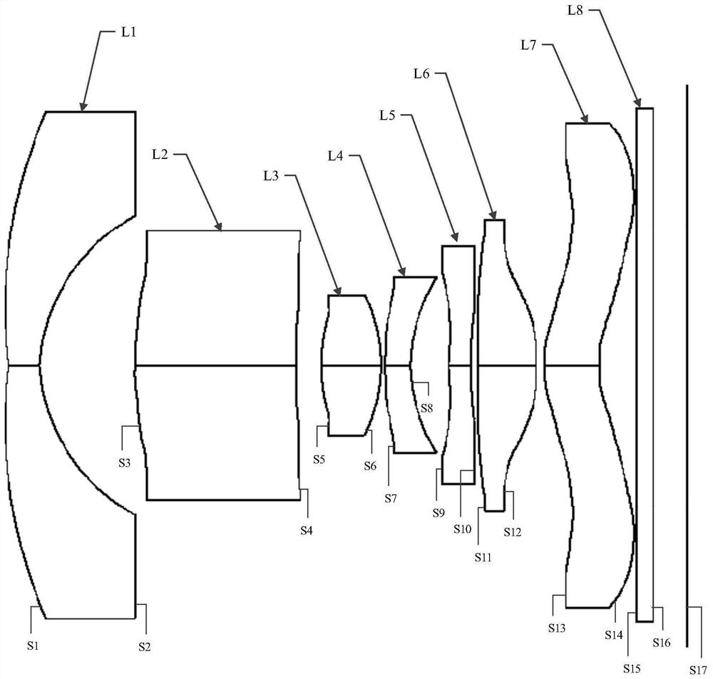
[0053] The optical imaging lens includes in sequence from the object side to the image side along the optical axis: first lens L1, second lens L2, third lens L3, fourth lens L4, fifth lens L5, sixth lens L6, seventh lens L7 and filter L8. The first lens L1 has negative refractive power, its object side S1 is convex, and its image side S2 is concave. The second lens L2 has positive refractive power, its object side S3 is convex, and its image side S4 is concave. The third lens L3 has positive refractive power, its object side S5 is convex, and its image side S6 is convex. The fourth lens L4 has negative refractive power, its object side S7 is convex, and its image side S8 is concave. The fifth lens L5 has negative refractive power, its object side S9 is concave, and its image side S10 is convex. The sixth lens L6 has positive refractive power, its object side S11 is convex, and its image side S12 is convex. The seventh lens L7 has positive refractive power, its object side ...

Embodiment 2

[0065] The optical imaging lens includes in sequence from the object side to the image side along the optical axis: first lens L1, second lens L2, third lens L3, fourth lens L4, fifth lens L5, sixth lens L6, seventh lens L7 and filter L8. The first lens L1 has negative refractive power, its object side S1 is convex, and its image side S2 is concave. The second lens L2 has negative refractive power, its object side S3 is concave, and its image side S4 is concave. The third lens L3 has positive refractive power, its object side S5 is convex, and its image side S6 is convex. The fourth lens L4 has negative refractive power, its object side S7 is convex, and its image side S8 is concave. The fifth lens L5 has negative refractive power, its object side S9 is concave, and its image side S10 is concave.

[0066] The sixth lens L6 has positive refractive power, its object side S11 is convex, and its image side S12 is convex.

[0067] The seventh lens L7 has positive refractive pow...


PUM


Abstract

The invention discloses an optical imaging lens, a camera module and electronic equipment, which belong to the technical field of optical elements. The optical imaging lens comprises a first lens, a second lens, a third lens, a fourth lens, a fifth lens, a sixth lens and a seventh lens, wherein the first lens has negative focal power, the object side surface of the first lens is a convex surface, and the image side surface is a concave surface; the second lens has focal power; the third lens has positive focal power, the object side surface is a convex surface, and the image side surface is a convex surface; the fourth lens has negative focal power, the object side surface is a convex surface, and the image side surface is a concave surface; the fifth lens has negative focal power; the sixth lens has positive focal power, the object side surface of the sixth lens is a convex surface, and the image side surface of the sixth lens is a convex surface; the seventh lens has positive focal power, the object side surface of the seventh lens is a convex surface, and the image side surface of the seventh lens is a convex surface; the maximum half field angle of the optical imaging lens is greater than or equal to 64.5 degrees; the Abbe number of the second lens is V2, the curvature radius value of the image side surface of the second lens is R4, and 2.5<V2/R4<3.5.

Description

technical field [0001] The application belongs to the technical field of optical elements, and in particular relates to an optical imaging lens, a camera module and electronic equipment. Background technique [0002] As users demand for shooting with a large field of view, more and more electronic devices are equipped with optical imaging lenses with ultra-wide angles. However, due to the large distortion of the ultra-wide-angle optical imaging lens, and the greater the angle, the greater the distortion, resulting in a more obvious distortion of the captured image, which makes the proportion of the image uncoordinated. At present, software is generally used to correct distortion of captured images. On the one hand, the ability of software to correct distortion is limited. On the other hand, software correction needs to consume additional power consumption, resulting in serious heating of electronic equipment during shooting. Contents of the invention [0003] The purpose ...

Claims


Application Information

Patent Timeline
Patent Type & Authority Applications(China)
IPC IPC(8): G02B13/00G02B13/18G02B13/06
CPCG02B13/0015G02B13/0045G02B13/06G03B30/00
Inventor 高雪
Owner VIVO MOBILE COMM HANGZHOU CO LTD
Why Eureka
Try Eureka