
Storage device for storage battery

A technology for storage devices and storage batteries, which is applied to battery components, circuits, electrical components, etc., and can solve the problems of inconvenient access to storage batteries and small spaces

Active Publication Date: 2021-11-30
河南工学院
View PDF4 Cites 0 Cited by
  • Summary
  • Abstract
  • Description
  • Claims
  • Application Information

AI Technical Summary

Problems solved by technology

[0005] In order to make up for the deficiencies of the existing technology, after placing multiple sets of batteries in the existing battery charging cabinet, when the innermost battery is fully charged, due to the narrow space of the partitions in the battery charging cabinet, it is difficult for people to go over the front end. The battery takes out the rear battery, which makes it very inconvenient to take the battery. The invention proposes a storage device for the battery

Method used


Image

  • Storage device for storage battery
  • Storage device for storage battery
  • Storage device for storage battery

Examples


Embodiment 1

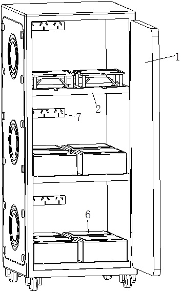
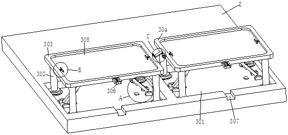
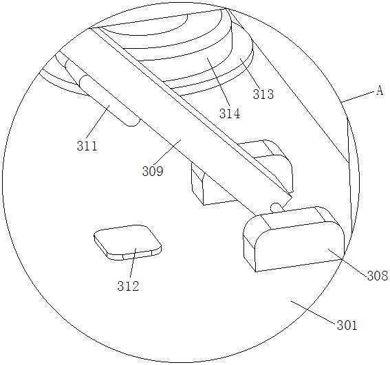
[0028] see Figure 1-6As shown, a battery storage device includes a storage cabinet 1, a partition 2, a battery body 6, a socket 7 and two storage slots 301; the inner wall of the storage cabinet 1 is fixed with a socket 7, and the storage cabinet 1 The inner wall of the separator 2 is fixedly installed with a battery body 6 on the top of the separator 2. The top of the separator 2 is provided with two storage slots 301, and the insides of the two storage slots 301 are respectively slidingly connected with Four sliding columns 302, and one end of two groups of sliding columns 302 are respectively fixedly installed with a first placing plate 303 and a second placing plate 304, and the first placing plate 303 and the second placing plate 304 are away from one end of the sliding column 302 There is a placement slot 305, and two card slots 310 are provided at the ends of the first placement plate 303 and the second placement plate 304 close to the sliding column 302, and four conv...

Embodiment 2

[0037] see Figure 7 As shown in Comparative Example 1, as another embodiment of the present invention, the side of the storage cabinet 1 close to the socket 7 is slidably inserted with a wire harness block 8, and the wire harness block 8 is in the shape of a "C"; During work, by pulling out the wire harness block 8 from the inner wall of the storage cabinet 1, insert the socket on the battery body 6 into the socket 7 at this time, and at this time, the electric wire on the battery body 6 is attached to the inner wall of the storage cabinet 1, And re-insert the wire harness block 8 into the storage cabinet 1 for clamping, so that the wire harness block 8 clamps the wires on the battery body 6 on the inner wall of the storage cabinet 1, thereby avoiding too many wires, too messy, and it is not easy to distinguish the battery body 6 Corresponding wires.

[0038] Working principle, by putting the battery body 6 into the placement groove 305 of the first placement plate 303, firs...


PUM


Abstract

The invention belongs to the field of storage batteries, and particularly relates to a storage device for a storage battery. The storage device comprises a storage cabinet, a partition plate, a storage battery body, a socket and two storage grooves, wherein the socket is fixedly mounted on the inner wall of the storage cabinet, the partition plate is fixedly mounted on the inner wall of the storage cabinet, the storage battery body is arranged at the top of the partition plate, the two storage grooves are formed in the top end of the partition plate, and four sliding columns are slidably connected to the interiors of the two storage grooves respectively. According to the invention, by rotating a supporting rod to a position under a clamping groove and then loosening a first placement plate, the first placement plate begins to fall back, the clamping groove in the first placement plate and the supporting rod are clamped and fixed, at the moment, the innermost storage battery body can be taken out through a space between the first placement plate and the partition plate, and after taking is completed, the supporting rod is pulled out of the clamping groove, and sliding columns drive the first placement plate to fall into a storage groove.

Description

technical field [0001] The invention relates to the field of batteries, in particular to a storage device for batteries. Background technique [0002] A battery is generally referred to as a battery for short, and a battery is a device that converts chemical energy into electrical energy, so it is also called a chemical battery. [0003] A battery is an electrochemical device that stores chemical energy and releases electrical energy when necessary. The battery can regenerate the internal active substances by charging, and store electrical energy as chemical energy; when it needs to be discharged, it converts chemical energy into electrical energy again. It is often placed in a battery charging cabinet, which can charge the battery. [0004] After placing multiple sets of batteries in the existing battery charging cabinet, when the innermost battery is fully charged, due to the narrow space of the partitions in the battery charging cabinet, it is difficult for people to go ...

Claims


Application Information

Patent Timeline
IPC IPC(8): H01M50/204H01M50/244H01M50/251H01M50/264H01M50/256
CPCH01M50/204H01M50/244H01M50/251H01M50/264H01M50/256Y02E60/10
Inventor 张英争段朝伟李婕吴标琪
Owner 河南工学院
Learn More