

Hinge structure
A hinge structure and hinge seat technology, which can be applied to building structures, wing leaf openers, buildings, etc., can solve the problems of unable to realize the closing preset action and single function, and achieve simplified internal layout, labor-saving rotating operation, and high arm strength. The effect of growth
- Summary
- Abstract
- Description
- Claims
- Application Information
AI Technical Summary
Problems solved by technology
Method used
Image

Examples
Embodiment Construction
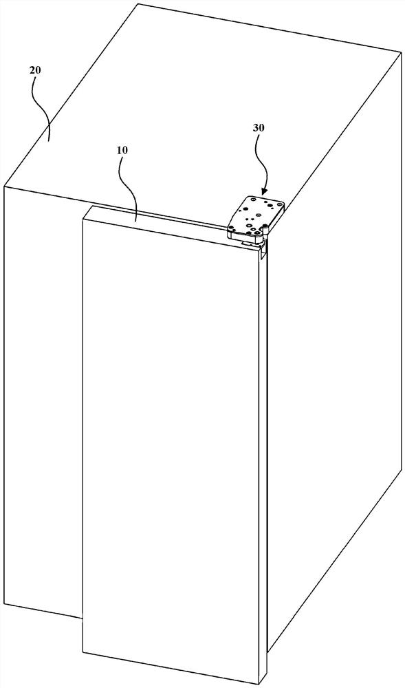
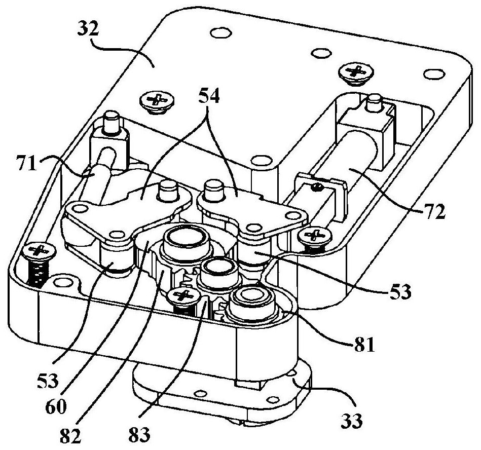
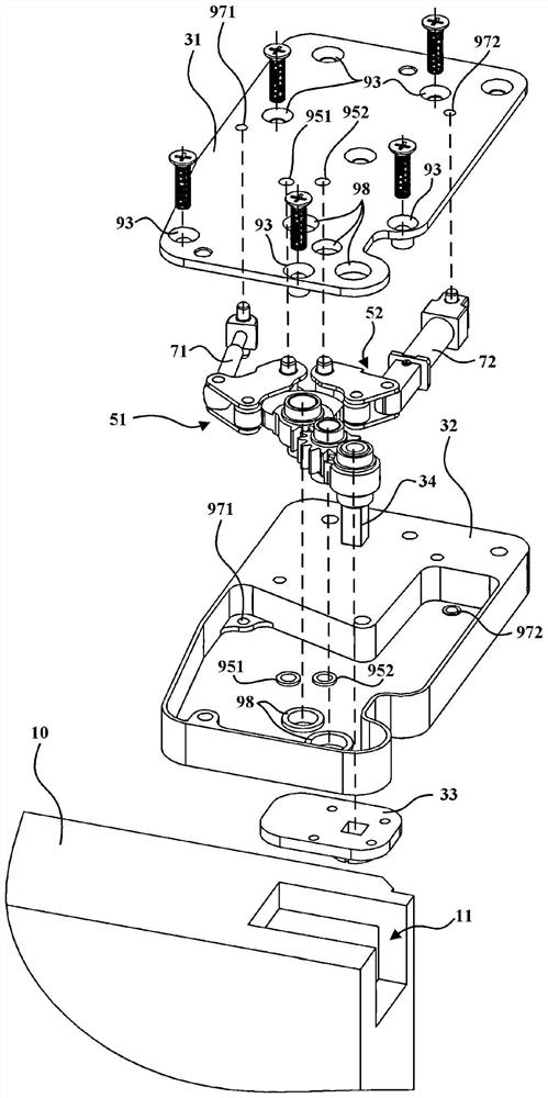
[0059] figure 1 is a schematic structural diagram of a refrigerator installed with a hinge structure 30 according to an embodiment of the present invention. figure 2 is a schematic structural view of the hinge structure 30 according to an embodiment of the present invention, wherein the hinge cover 31 is omitted in order to illustrate the internal arrangement of the hinge structure 30 .
[0060]One embodiment of the present invention provides a hinge structure 30 . The hinge structure 30 may generally include a rotating shaft 34 and a hinge seat 32 . The rotating shaft 34 is used to connect the first part 10 , the hinge seat 32 is used to connect the second part 20 , and the first part 10 can move relative to the second part 20 . The first component 10 can be as figure 1 As shown in the refrigerator door or the door body or window of other furniture / household appliances, etc., the second part 20 can be as figure 1 Shown refrigerator box or other furniture / main body of h...
PUM
 Abstract
Description
Claims
Application Information