Anti-impact and wear-resistant electric heater

An electric heater, wear-resistant technology, applied in the direction of ohmic resistance heating parts, etc., can solve the problems of inability to adjust the electric heater, inconvenient use of containers of different sizes, and affect the heating effect, etc., to achieve safe and efficient operation and practicality strong effect

Pending Publication Date: 2021-12-03
江苏普力西机电有限公司
View PDF1 Cites 0 Cited by
  • Summary
  • Abstract
  • Description
  • Claims
  • Application Information

AI Technical Summary

Problems solved by technology

[0003] The existing electric heater still has some disadvantages during use, for example, the electric heater cannot be adjusted during use, and it is not convenient for the electric heater to be used for containers of different sizes, making it easy to appear The phenomenon of falling affects its normal heating effect, thereby reducing the applicability of the electric heater, which cannot meet people's needs well. In view of the above situation, technological innovation is carried out on the basis of the existing electric heater
[0004] In today's technical means, publication number: a kind of anti-shock and wear-resistant electric heater announced by CN210093598U has effectively improved the above problems, but still has the situation of inconvenience in use, and the traditional anti-shock and wear-resistant electric heater is in In practical applications, the inner cylinder is often installed with multiple bolts distributed in a ring, which is not convenient for safe and convenient disassembly and assembly of the inner cylinder, and has poor practicability. Therefore, it is necessary to propose a new anti-impact and wear-resistant electric heating device, thus effectively solving the above inconvenience

Method used


Image

  • Anti-impact and wear-resistant electric heater
  • Anti-impact and wear-resistant electric heater
  • Anti-impact and wear-resistant electric heater

Examples


Embodiment

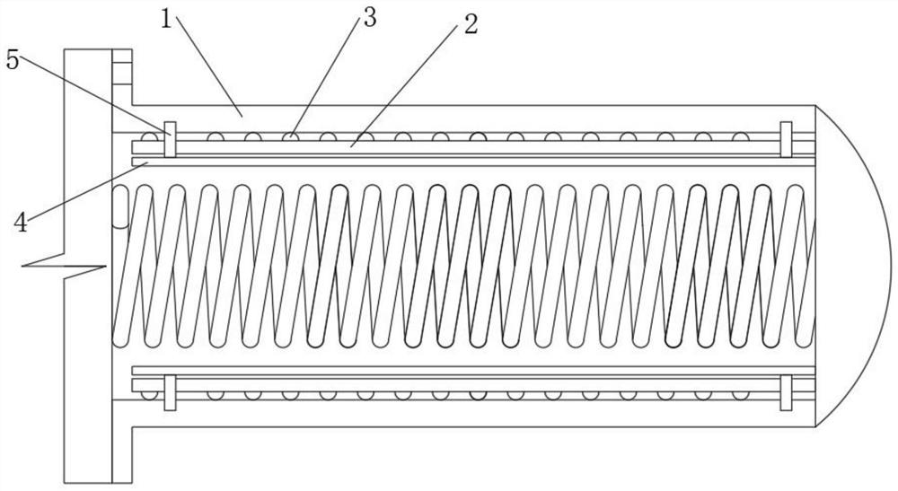
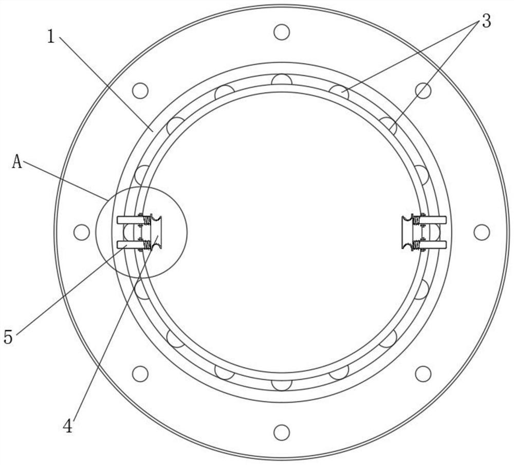
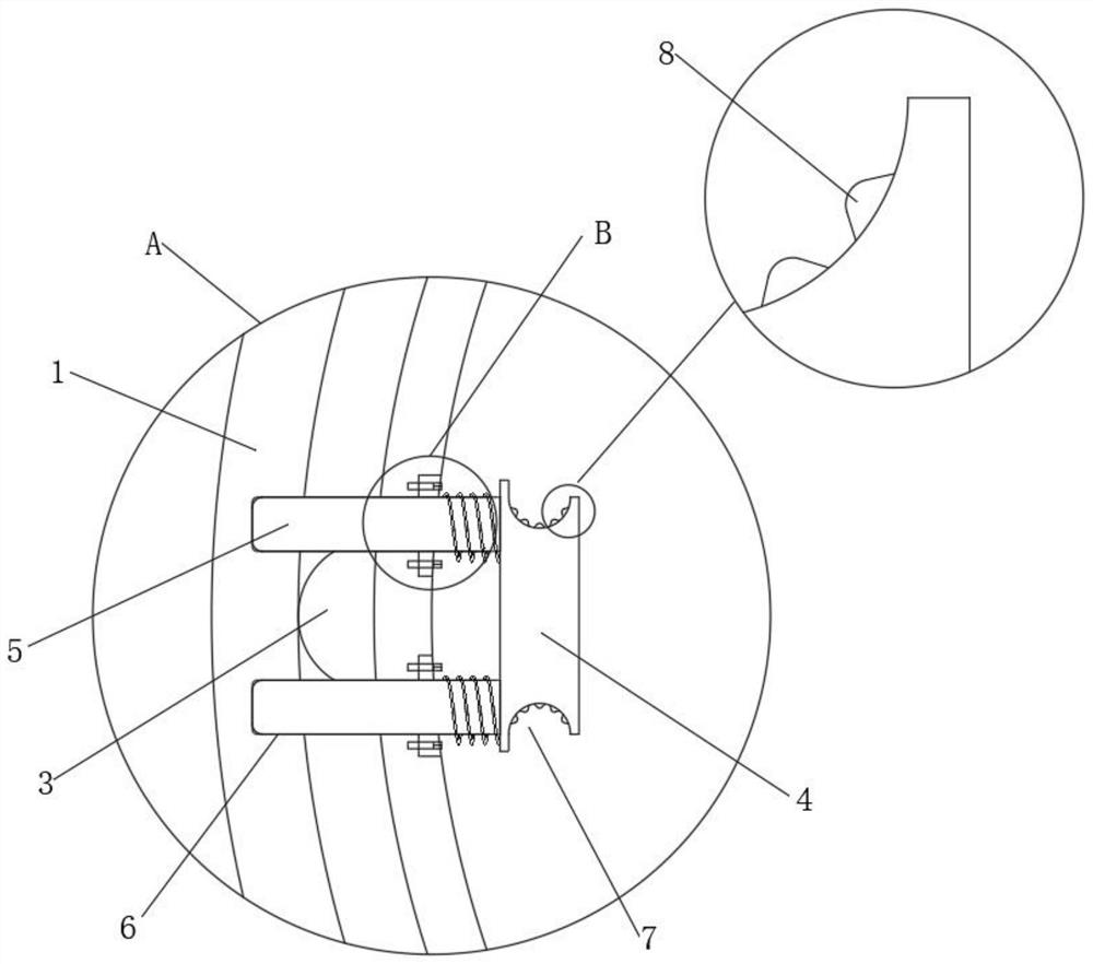
[0020] see Figure 1-4 , the present invention provides the following technical solutions: an anti-shock and wear-resistant electric heater, including an outer cylinder 1, an inner cylinder 2 and a bump 3, the outer cylinder 1 is sleeved outside the inner cylinder 2, and the outer wall of the inner cylinder 2 A plurality of bumps 3 are distributed, and an installation assembly is provided on the inner side of the inner cylinder 2. The installation assembly includes an installation plate 4 and a positioning post 5. There are two installation plates 4 in total, and the two installation plates 4 are located within the center of the inner cylinder 2. The positions are distributed symmetrically. One side of a single mounting plate 4 is connected with four positioning posts 5, and the four positioning posts 5 are arranged at four corners of a rectangle. Positioning cards are provided at positions corresponding to the positioning posts 5 in the outer cylinder 1. Groove 6, the install...


PUM


Abstract

The invention belongs to the technical field of electric heaters, and particularly relates to an anti-impact and wear-resistant electric heater. The electric heater comprises an outer cylinder, an inner cylinder and protruding blocks, the outer cylinder is arranged outside the inner cylinder in a sleeving mode, the protruding blocks are distributed on the outer wall of the inner cylinder, a mounting assembly is arranged on the inner side of the inner cylinder and comprises mounting plates and a positioning clamping column, and the number of the mounting plates is two. Through the arrangement of the mounting plates in the inner cylinder and the cooperation of the inserting effect of the positioning clamping columns on the mounting plates in the positioning clamping grooves under the effect of return springs, the inner cylinder can be rapidly positioned in the outer cylinder when being collected into the outer cylinder, and the situation that a large number of bolts are used for operation is avoided, so time and labor are saved; and meanwhile, through the grooves formed in the mounting plates and the anti-skid protrusions distributed in the grooves, the worker can conveniently hold the mounting plates by hand to pull one ends of the positioning clamping columns outwards to be separated from the positioning clamping grooves, and pulling is synchronously conducted, so that the inner cylinder can be conveniently pulled out of the outer cylinder, and practicability is high.

Description

technical field [0001] The invention belongs to the technical field of electric heaters, in particular to an impact-resistant and wear-resistant electric heater. Background technique [0002] Electric heating is a process of converting electrical energy into thermal energy, while an electric heater is a heating device that converts electrical energy into thermal energy to heat up, keep warm, and heat flowing liquid and gaseous media. With the continuous development of science and technology With the continuous progress of society, the use of electric heaters is becoming more and more extensive, which also promotes the continuous improvement and perfection of electric heaters. [0003] The existing electric heater still has some disadvantages during use, for example, the electric heater cannot be adjusted during use, and it is not convenient for the electric heater to be used for containers of different sizes, making it easy to appear The phenomenon of falling affects its no...

Claims


Application Information

Patent Timeline
IPC IPC(8): H05B3/02
CPCH05B3/02
Inventor 王来凶殷士江王庆红
Owner 江苏普力西机电有限公司
Why Eureka
Try Eureka