Sensor inner core mounting and press-fitting mechanism
A sensor and inner core technology, applied in the field of sensor inner core installation and press-fitting mechanism, can solve the problems of heavy press-fitting work, easy to affect the production quality of sensors, and low efficiency, and achieve convenient fixing, simple operation, and lifting press-fitting efficiency effect
- Summary
- Abstract
- Description
- Claims
- Application Information
AI Technical Summary
Problems solved by technology
Method used
Image

Examples
Embodiment 1
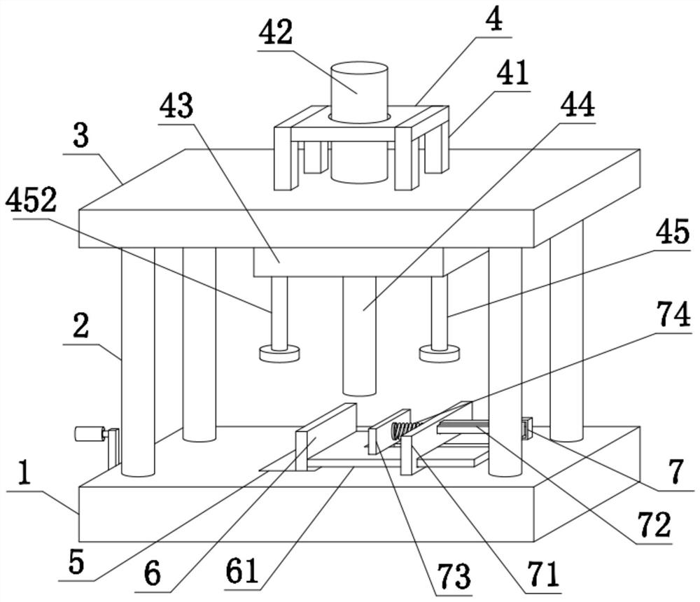
[0037] refer to Figure 1-4 , a sensor inner core mounting and pressing mechanism described in this embodiment includes a base 1, the outer side of the upper end of the base 1 is fixedly connected with a column 2, the upper end of the column 2 is fixedly connected with a top cover 3, and the upper end of the top cover 3 is provided with Pressure mechanism 4, the upper left side of the base 1 is provided with an adjustment mechanism 5, the upper left side of the base 1 is slidably connected with a moving plate 6 through the adjustment mechanism 5, the lower end of the side wall of the moving plate 6 is fixedly connected with a support plate 61, the base 1 There is a clamping mechanism 7 on the right side of the upper end, and the support plate 61 is slidably connected with the clamping mechanism 7; the inner core can be press-fitted through the pressure mechanism 4, and the clamping mechanism 7 can be used to clamp the material through the moving plate 6 , to avoid the deviation ...
Embodiment 2
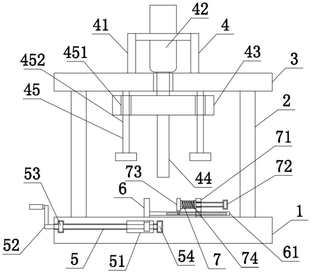
[0039] refer to figure 2 , on the basis of Embodiment 1, in order to achieve the purpose of press-fitting work, this embodiment has carried out innovative design on the pressure mechanism 4, specifically, the pressure mechanism 4 includes a bracket 41, a cylinder 42, a platen 43, and a pressing rod 44 With the first positioning assembly 45, the bracket 41 is fixedly installed on the upper end of the platen 43, the cylinder 42 is fixedly installed inside the bracket 41, the output end of the cylinder 42 runs through the top cover 3, and the platen 43 is fixedly connected to the output end of the cylinder 42, The pressure rod 44 is fixedly connected to the lower end of the platen 43, and the lower end of the pressure rod 44 is movably connected with the support plate 61, and the first positioning assembly 45 is arranged on both sides of the upper end of the platen 43; the position of the fixed cylinder 42 is played by the bracket 41 , so that the cylinder 42 can drive the plate...
Embodiment 3
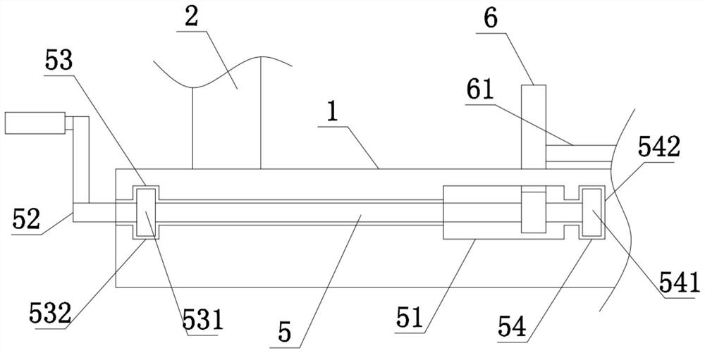
[0042] refer to image 3 In this embodiment, on the basis of Embodiment 2, in order to achieve the purpose of adjusting the position of the moving plate 6, this embodiment has innovatively designed the adjustment mechanism 5. Specifically, the adjustment mechanism 5 includes a first chute 51, a screw rod 52, The first limiting assembly 53 and the second limiting assembly 54, the first chute 51 is opened on the left side of the upper end of the base 1, the lower end of the moving plate 6 is slidably connected to the inside of the first chute 51, and the screw rod 52 is rotatably connected to the base 1, one end of the screw rod 52 runs through the base 1, one end of the screw rod 52 extends into the inside of the first chute 51, one end of the screw rod 52 runs through the moving plate 6, and the outer wall of the screw rod 52 is threadedly connected with the moving plate 6, the first The limit assembly 53 is arranged on the left side of the outer wall of the screw rod 52, and ...
PUM
 Abstract
Description
Claims
Application Information
 - Generate Ideas
- Intellectual Property
- Life Sciences
- Materials
- Tech Scout
- Unparalleled Data Quality
- Higher Quality Content
- 60% Fewer Hallucinations
Browse by: Latest US Patents, China's latest patents, Technical Efficacy Thesaurus, Application Domain, Technology Topic, Popular Technical Reports.
© 2025 PatSnap. All rights reserved.Legal|Privacy policy|Modern Slavery Act Transparency Statement|Sitemap|About US| Contact US: help@patsnap.com