Modularized road laying device
A laying device and modular technology, applied in the field of road engineering, can solve the problems of complex and cumbersome laying steps, difficulty in meeting its requirements, long construction time, etc., achieve the effect of strong laying continuity, not easy to slip, and improve construction efficiency
- Summary
- Abstract
- Description
- Claims
- Application Information
AI Technical Summary
Problems solved by technology
Method used
Image
Examples
specific Embodiment approach 1
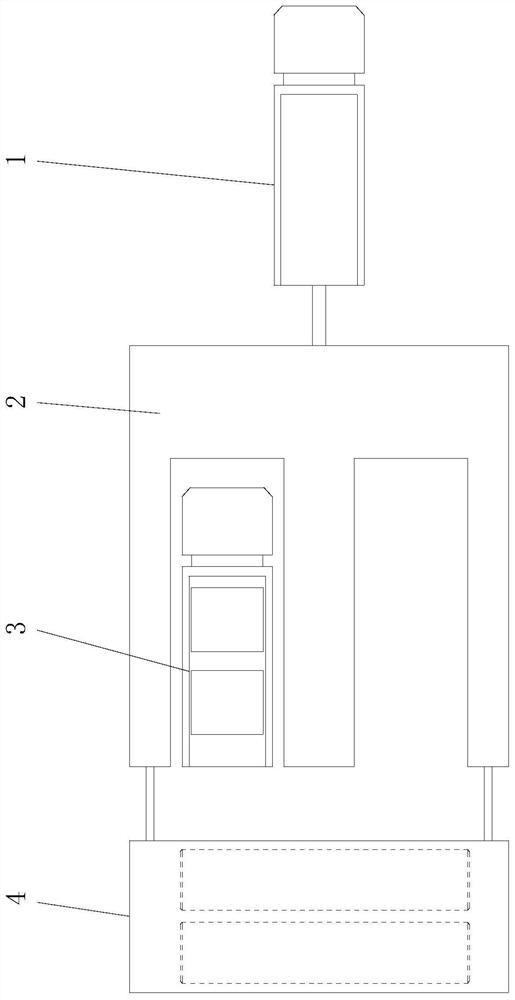
[0023] Specific implementation mode one: combine Figure 1 to Figure 8 Describe this embodiment, a kind of modularized road laying device described in this embodiment includes tractor 1, automatic laying device 2, transport vehicle 3 and flattening device 4, tractor 1, automatic laying device 2, flattening device 4 are composed of The front to back is connected sequentially, and the transport vehicle 3 moves synchronously in the automatic laying device 2 .
specific Embodiment approach 2
[0024] Specific implementation mode two: combination Figure 1 to Figure 8 Describe this embodiment, the automatic laying device 2 of a kind of modularized road laying device described in this embodiment includes car body 2-1, two lifting units and four moving wheels 2-2; Installed on the upper surface of the car body 2-1 from front to back, the car body 2-1 is a rectangular plate body arranged horizontally, and the four moving wheels 2-2 are respectively installed on the four corners of the lower surface of the car body 2-1 , the rear end of the car body 2-1 has a first gap 2-1-1 and a second gap 2-1-2 side by side along the width direction, and the transport vehicle 3 is connected to the car body 2 in the first gap 2-1-1. -1 synchronized movement. Other components and connections are the same as those in the first embodiment.
specific Embodiment approach 3
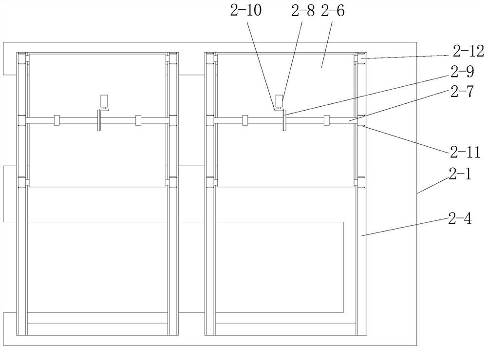
[0025] Specific implementation mode three: combination Figure 1 to Figure 8 To illustrate this embodiment, each lifting unit of a modular road paving device in this embodiment includes a support frame 2-3, a traveling vehicle mechanism, two racks 2-4 and four booms 2- 5. The support frame 2-3 is installed on the upper surface of the car body 2-1, and the two racks 2-4 are installed side by side and parallel on the top of the support frame 2-3, and the center line of the rack 2-4 along the length direction Vertical to the center line of the car body 2-1 along the length direction, the traveling carriage mechanism is installed on two racks 2-4, and the four booms 2-5 are rectangularly mounted on the lower surface of the traveling carriage mechanism. Other components and connections are the same as those in the second embodiment.
PUM
 Abstract
Description
Claims
Application Information
 - R&D
- Intellectual Property
- Life Sciences
- Materials
- Tech Scout
- Unparalleled Data Quality
- Higher Quality Content
- 60% Fewer Hallucinations
Browse by: Latest US Patents, China's latest patents, Technical Efficacy Thesaurus, Application Domain, Technology Topic, Popular Technical Reports.
© 2025 PatSnap. All rights reserved.Legal|Privacy policy|Modern Slavery Act Transparency Statement|Sitemap|About US| Contact US: help@patsnap.com


