Composite type pavement structure and pavement method thereof

A composite and pavement technology, which is applied to cohesive pavement paved on site, bridge parts, roads, etc., can solve problems such as easy peeling of the waterproof adhesive layer, shorten the service life of the pavement, and weaken the strength of the underlying layer. Improve the anti-fatigue and anti-reflection crack performance, improve the stiffness of the bridge deck, and reduce the thickness

Active Publication Date: 2009-12-09
广州大象超薄路面技术开发有限公司
View PDF0 Cites 25 Cited by
  • Summary
  • Abstract
  • Description
  • Claims
  • Application Information

AI Technical Summary

Problems solved by technology

In the prior art, a certain amount of emulsified asphalt, modified asphalt or other waterproof coatings are often used as the waterproof bonding layer of the above-mentioned lower bearing layer. Due to the hydrophilicity of the lower bearing material, under the long-term driving load, the waterproof bonding The layer is easy to peel off and loosen, causing rainwater to infiltrate
As a result, the ...

Method used


Image

  • Composite type pavement structure and pavement method thereof
  • Composite type pavement structure and pavement method thereof
  • Composite type pavement structure and pavement method thereof

Examples


Embodiment 1

[0047] Composite Pavement Structure and Construction Technology of Sliding Connection on Old Cement Concrete Pavement

[0048] (1) Structure and material

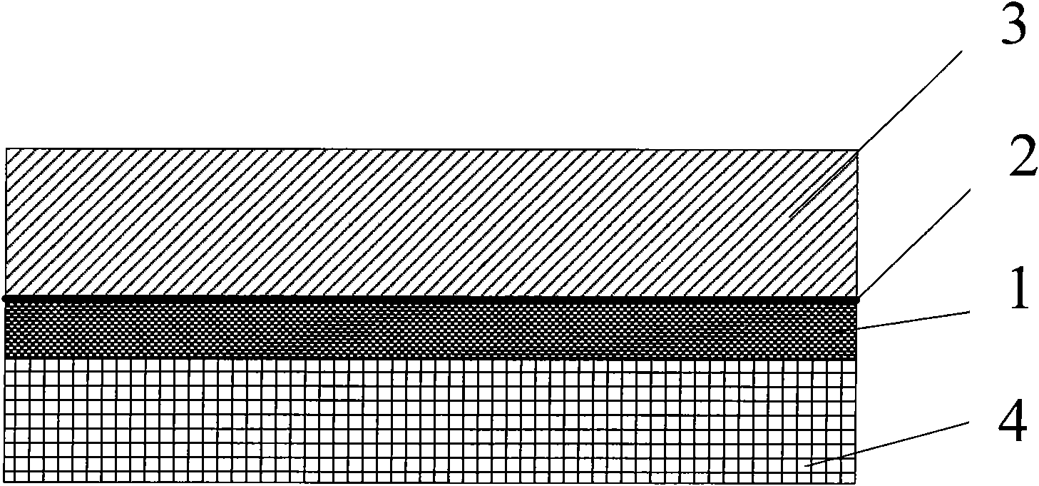
[0049] use figure 1 The pavement structure shown includes a base plate 1 , an adhesive layer 2 on the plate and an asphalt surface layer 3 from bottom to top.

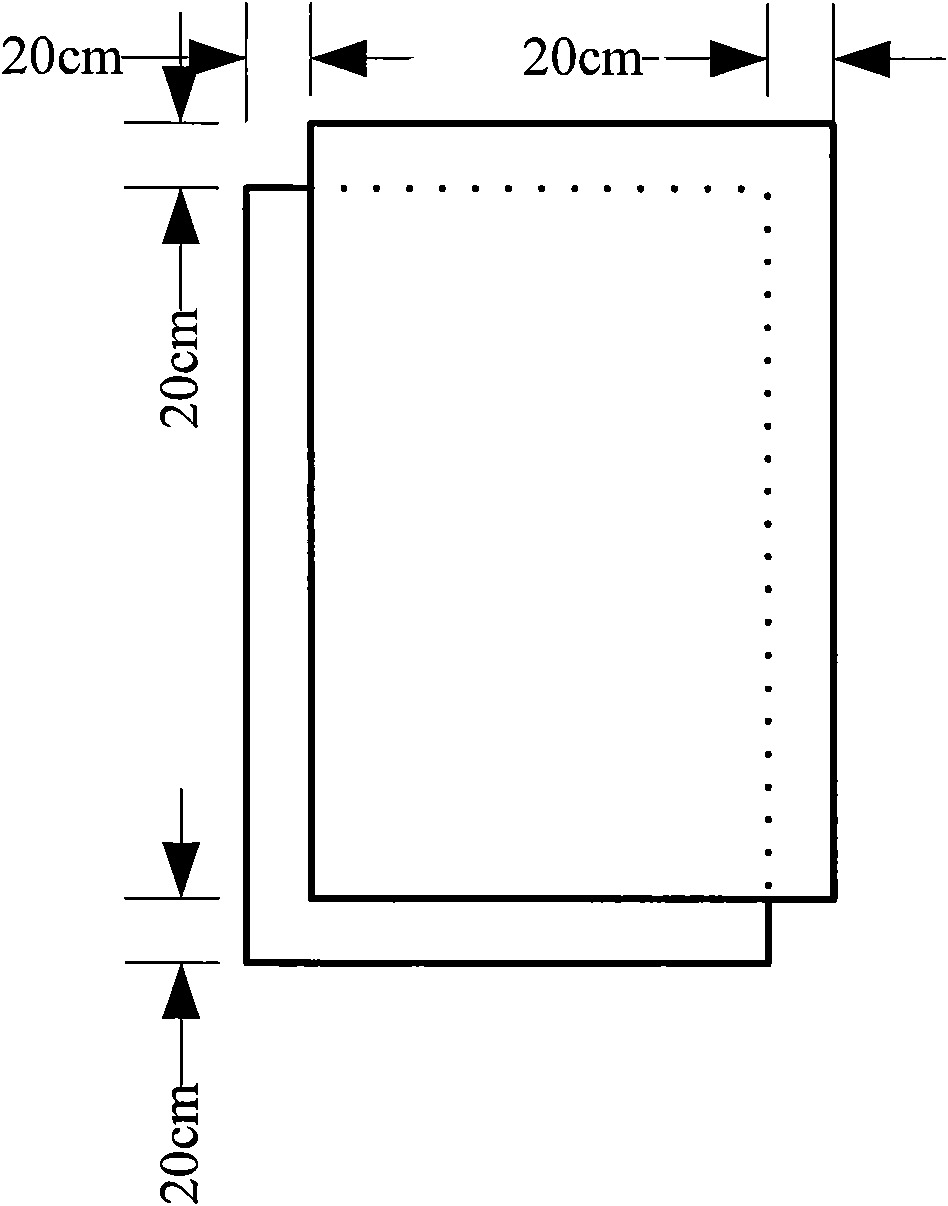
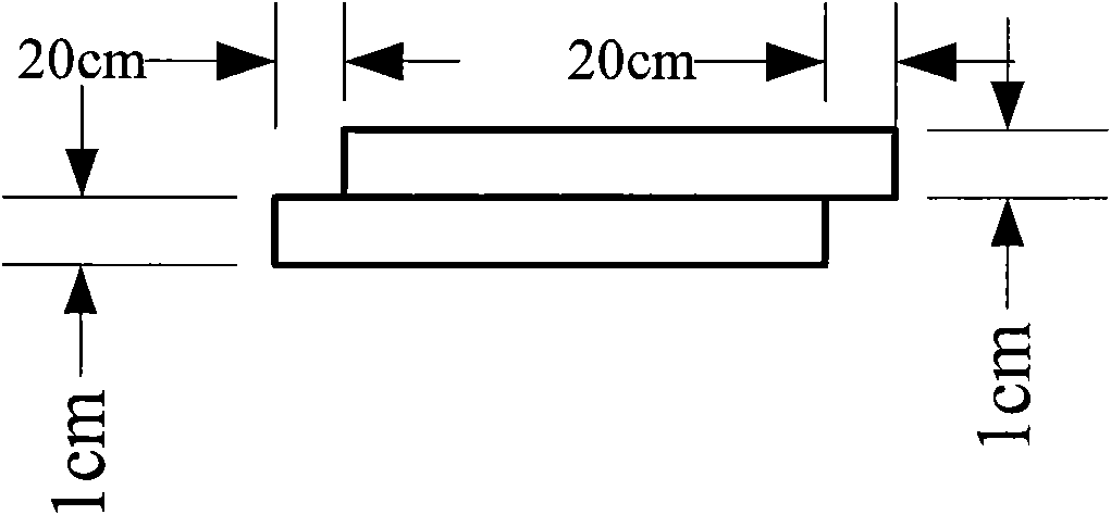
[0050] Substrate 1 uses a glass steel plate with a thermal expansion coefficient close to that of cement concrete; the technical specifications of the substrate of fiber-reinforced composite materials are shown in Table 1, as shown in figure 2 , image 3 As shown, the substrate 1 is an integrated structure, and the shape of the substrate 1 is that two overlapping cuboids are staggered in parallel along the contact surface, and the original overlapping sides are all staggered by the same distance, and the distance is 20 cm. The thickness of the substrate is 20mm; the length of each board is 30m and the width is 3.75m;

[0051] The sticky layer on the board adopt...

Embodiment 2

[0066] Composite pavement structure bonded to steel bridge deck with epoxy resin and its construction technology

[0067] (1) Structure and material

[0068] use Figure 5 The pavement structure shown is composed of a base plate 1 , an adhesive layer 2 on the upper plate, an adhesive layer 7 under the plate and an asphalt surface layer 3 . The substrate adopts a glass steel plate with a thermal expansion coefficient close to that of the steel plate. See Table 1 for technical indicators. Such as figure 2 , image 3 As shown, the substrate 1 is an integrated structure, and the shape of the substrate 1 is that two overlapping cuboids are staggered in parallel along the contact surface, and the original overlapping sides are all staggered by the same distance, and the distance is 20 cm. The thickness of the substrate is 20mm; the length of each board is 30m and the width is 3.75m.

[0069] The sticky layer on the board adopts a sprinkling amount of 2.0kg / m 2 SBS modified a...


PUM

PropertyMeasurementUnit
Thicknessaaaaaaaaaa
Thicknessaaaaaaaaaa
Thicknessaaaaaaaaaa

Abstract

The invention discloses a composite type pavement structure and a pavement method, and relates to a road engineering structure and a construction method thereof. In the invention, the thermal expansion coefficient, the cement concrete and the fiber-reinforced composite material substrate which performance is near to the steel plate are adopted to reinforce for the bottom surface of the asphalt layer; thus improving the performance of anti-fatigue and anti-reflecting crack of the asphalt surface course, effectively preventing the lower bearing layer from being eroded due to infiltration of the rain water from the asphalt surface course, avoiding bonding problem between the asphalt surface course and the cement concrete or the steel plate, increasing stiffness of the steel bridge surface, and particularly reinforcing the steel bridge surface the steel plate of which has insufficient thickness, so as to reduce the thickness of the asphalt surface course, avoid the damages, such as cracking and falling of the asphalt pavement layer caused by the insufficient thickness of the steel bridge surface and the like.

Description

technical field [0001] The invention relates to a road engineering structure and a construction method thereof, in particular to a composite pavement structure paved on cement concrete road surfaces, cement concrete bridge decks and steel bridge decks and a construction method thereof, in particular to a composite pavement structure Pavement structures and their paving methods. Background technique [0002] For a long time, the problem of bonding and waterproofing between the asphalt pavement and the cement concrete pavement of the underlying layer, the cement concrete bridge deck and the steel bridge deck has been a technical problem that has not been well resolved. In the prior art, a certain amount of emulsified asphalt, modified asphalt or other waterproof coatings are often used as the waterproof bonding layer of the above-mentioned lower bearing layer. Due to the hydrophilicity of the lower bearing material, under the long-term driving load, the waterproof bonding The...

Claims


Application Information

Patent Timeline
IPC IPC(8): E01C7/32E01D19/12
Inventor 葛折圣张肖宁
Owner 广州大象超薄路面技术开发有限公司
Why Eureka
Try Eureka