Al technical title is built by PatSnap Al team. It summarizes the technical point description of the patent document.
A technology of new energy vehicles and power batteries, which is applied to the parts of electrical measuring instruments, instruments, and measuring electricity. It can solve problems such as leakage, power cord damage, etc., so as to prolong the service life, ensure normal operation, and practicability. strong effect
Pending Publication Date: 2021-12-07
SHENZHEN ANCHE TECH
View PDF0 Cites 0 Cited by
Summary
Abstract
Description
Claims
Application Information
AI Technical Summary
This helps you quickly interpret patents by identifying the three key elements:
Problems solved by technology
Method used
Benefits of technology
Problems solved by technology
[0003] At present, when the existing new energy vehicle power battery detector is actually used, especially in the process of testing, it is usually necessary to use a power cord to connect the power battery and the charge and discharge detector. However, due to the high height of the charge and discharge detector, the power supply The power cord is often bent on the charge and discharge detector, which is extremely easy to cause damage to the power cord, and even serious accidents such as leakage, which need to be improved
Method used
Image
Click on the blue label to locate the original text in one second.
Reading with bidirectional positioning of images and text.
Examples
Embodiment Construction
[0026] In order to more clearly understand the above objects, features and advantages of the present invention, the present invention will be further described below in conjunction with the accompanying drawings and embodiments. It should be noted that, in the case of no conflict, the embodiments of the present application and the features in the embodiments can be combined with each other.
[0027] In the following description, many specific details are set forth in order to fully understand the present invention. However, the present invention can also be implemented in other ways than described here. Therefore, the present invention is not limited to the specific embodiments disclosed below. limit.
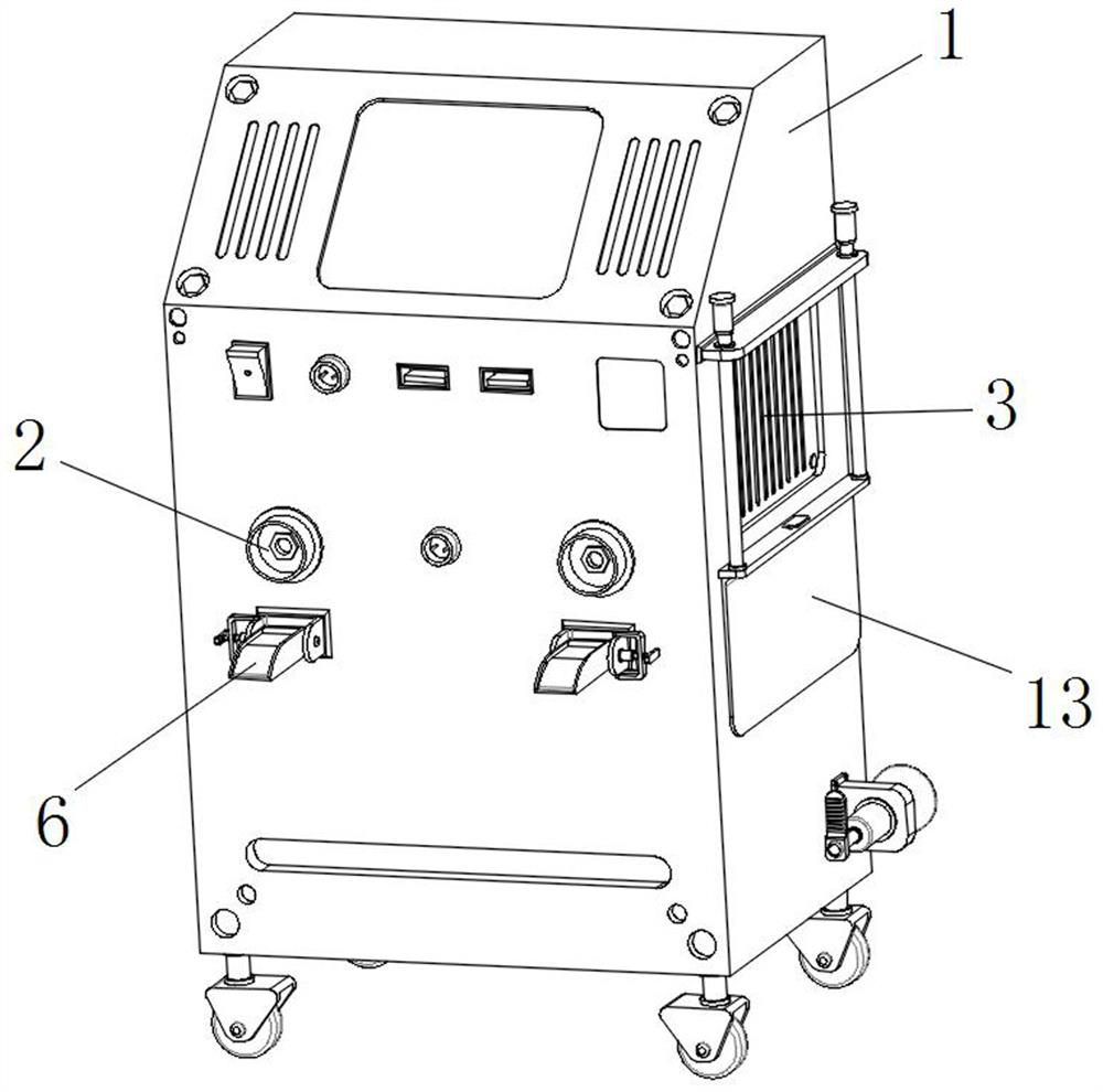
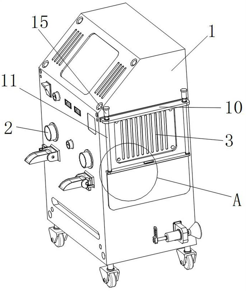
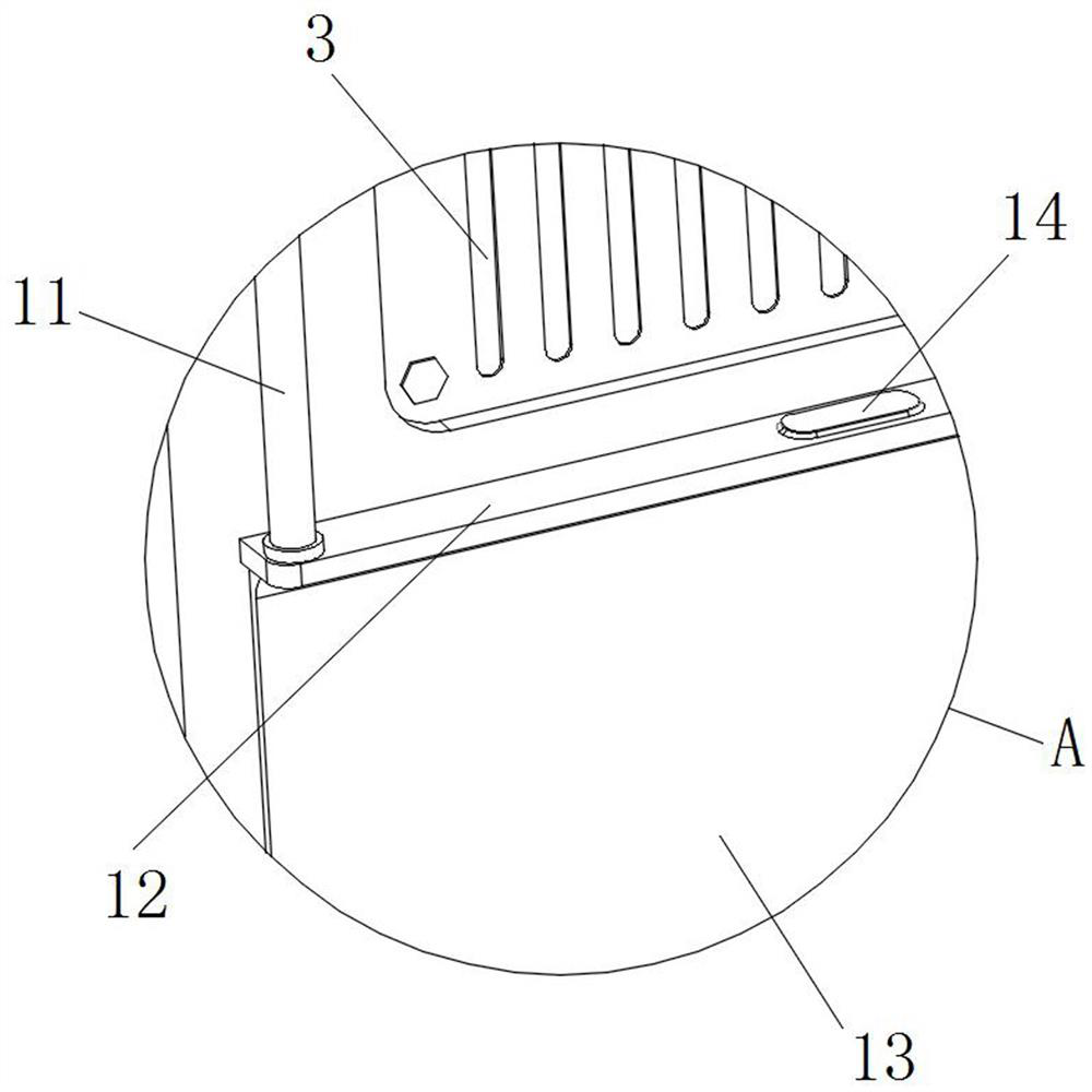
[0028] see Figure 1-7 , the present invention provides a technical solution: a new energy vehicle power battery detector, including a charge and discharge detector 1, a charging port 2, a heat dissipation port 3, a bump 4, a rotating rod 5, a lifting plate 6, a sliding rod 7 ...
PUM
Abstract
The invention provides a new energy automobile power battery detector, and relates to the technical field of battery detection. The new energy automobile power battery detector comprises a charging and discharging detector, a charging port, a heat dissipation port, a convex block, a rotating rod, a lifting plate, a sliding rod and a clamping block, the surface of the charging and discharging detector is provided with the charging port, the side surface of the charging and discharging detector is provided with the heat dissipation port, a convex block is fixedly installed at the position, close to the charging port, of the surface of the charging and discharging detector, the rotating rod is arranged on the side face of the convex block in a penetrating mode, the lifting plate is fixedly installed on the surface of the rotating rod, the sliding rod is arranged at one end of the rotating rod in a penetrating mode, and the clamping block is fixedly installed on the surface of the sliding rod. A power line can be well supported through the arranged supporting plate, in this way, in the testing process, the situation that the power line is damaged due to the fact that the bending amplitude of the power line is too large can be avoided, the service life of the power line is prolonged, when the supporting plate is not used, the supporting plate can be folded only by pulling the pull handle outwards, and actual use is facilitated.
Description
technical field [0001] The invention relates to the technical field of battery detection, in particular to a new energy vehicle power battery tester. Background technique [0002] In order to ensure the normal use of automotive power batteries, it is often necessary to conduct a capacity checking discharge test on the automotive power batteries on a regular basis or in a timely manner as needed, so as to replace individual failed or near-failed single batteries at an early stage to ensure the integrity of the entire battery pack. Effectiveness, in this process, you need to use the car power battery tester. [0003] At present, when the existing new energy vehicle power battery detector is actually used, especially in the process of testing, it is usually necessary to use a power cord to connect the power battery and the charge and discharge detector. However, due to the high height of the charge and discharge detector, the power supply The power cord is often bent on the ch...
Claims
Application Information
Patent Timeline
Application Date:The date an application was filed.
Publication Date:The date a patent or application was officially published.
First Publication Date:The earliest publication date of a patent with the same application number.
Issue Date:Publication date of the patent grant document.
PCT Entry Date:The Entry date of PCT National Phase.
Estimated Expiry Date:The statutory expiry date of a patent right according to the Patent Law, and it is the longest term of protection that the patent right can achieve without the termination of the patent right due to other reasons(Term extension factor has been taken into account ).
Invalid Date:Actual expiry date is based on effective date or publication date of legal transaction data of invalid patent.