Supercharge Your Innovation With Domain-Expert AI Agents!

Method for controlling display screen and control circuit thereof

A technology for controlling circuits and display screens, used in static indicators, instruments, etc., and can solve the problems of long-term excessive and reverse bias of light-emitting diodes

Pending Publication Date: 2021-12-07
NOVATEK MICROELECTRONICS CORP
View PDF0 Cites 1 Cited by
  • Summary
  • Abstract
  • Description
  • Claims
  • Application Information

AI Technical Summary

Problems solved by technology

[0007] Therefore, the main purpose of the present invention is to provide a novel driving method and its control circuit for passive matrix light-emitting diode (PM-LED) display screens, to solve the problem of long-term and / or The problem of excessive reverse bias

Method used


Image

  • Method for controlling display screen and control circuit thereof
  • Method for controlling display screen and control circuit thereof
  • Method for controlling display screen and control circuit thereof

Examples


Embodiment Construction

[0046] The problem of image sticking encountered on Passive Matrix Light-Emitting Diode (PM-LED) displays can be divided into upstream image sticking and downstream image sticking , the causes and solutions are explained below.

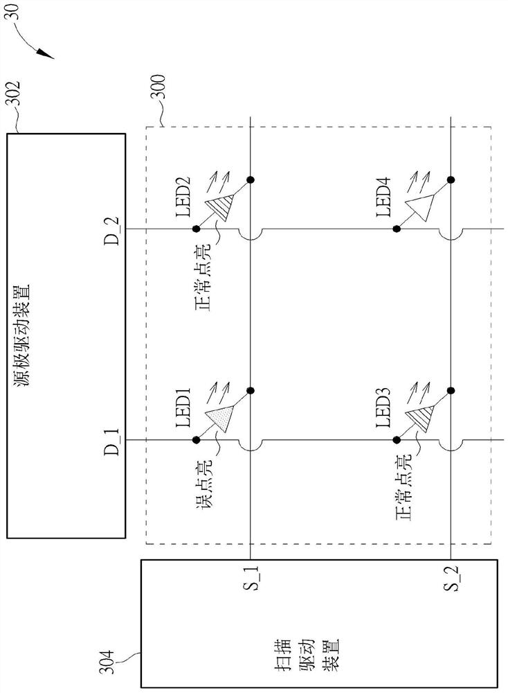
[0047] Please refer to image 3 , image 3 is a schematic diagram showing the control system 30 . The display control system 30 includes a display screen 300 , a source driver 302 and a scan driver 304 . The display screen 300 includes a plurality of scanning lines, a plurality of data lines and a plurality of sub-pixels, for simplicity, image 3 Only 4 sub-pixels and their corresponding light emitting diodes LED1 - LED4 are shown. The four light-emitting diodes LED1-LED4 are respectively included in four adjacent sub-pixels to form a 2×2 array. Under the structure of the passive matrix LED display, the LEDs LED1 - LED4 are controlled by the data lines D_1 , D_2 and the scan lines S_1 , S_2 . The data lines D_1 and D_2 are coupled to the source ...


PUM


Abstract

The invention discloses a method for controlling a display screen and a control circuit thereof. The display screen comprises a plurality of sub-pixels and a plurality of scanning lines coupled to the sub-pixels. The method comprises the following steps of scanning a first scanning line in the plurality of scanning lines in a sub-frame period of a display frame period so as to turn on at least one sub-pixel coupled to the first scanning line in the plurality of sub-pixels; and discharging a second scanning line in the plurality of scanning lines in a non-display period after the sub-frame period, wherein the second scanning line is different from the first scanning line.

Description

technical field [0001] The present invention relates to a method for controlling a display screen and a control circuit thereof, in particular to a method for controlling a passive matrix light-emitting diode (PM-LED) display screen and a related control circuit. Background technique [0002] Light-Emitting Diodes (LEDs) are widely used in displays of various electronic devices, such as TV screens, computer monitors, and portable systems, such as mobile phones, handheld game consoles, and personal digital assistants. Please refer to figure 1 , figure 1 It is a schematic diagram of a driving structure of a passive matrix light-emitting diode (PM-LED) display, which includes a certain current source 100 connected to a plurality of light-emitting diodes (LED1-LED4), and each light-emitting diode LED1-LED4 is respectively connected to a Switches SW1-SW4. Under the control of the switches SW1-SW4, each light-emitting diode LED1-LED4 can be driven in time division. [0003] Pl...

Claims


Application Information

Patent Timeline
Patent Type & Authority Applications(China)
IPC IPC(8): G09G3/32
CPCG09G3/32G09G2300/06G09G3/3216G09G3/3266G09G2310/0251
Inventor 林俊甫程智修马佑升林晋毅
Owner NOVATEK MICROELECTRONICS CORP
Features
  • R&D
  • Intellectual Property
  • Life Sciences
  • Materials
  • Tech Scout
  • Unparalleled Data Quality
  • Higher Quality Content
  • 60% Fewer Hallucinations
Learn More