Scanning densitometry system with adjustable X-ray tube current

a densitometry and x-ray tube technology, applied in the field of dual energy xray imaging and measuring equipment, can solve the problems of needlessly slow scan, complex multi-speed scanning mechanism and actuation device, and scan speed, and achieve the effect of effective continuous adjustmen

Inactive Publication Date: 2002-08-20
LUNAR CORP
View PDF15 Cites 141 Cited by
  • Summary
  • Abstract
  • Description
  • Claims
  • Application Information

AI Technical Summary

Benefits of technology

to provide a method of controlling x-ray signals t

Problems solved by technology

A disadvantage to such systems is that they require a complex multi-speed scanning mechanisms and actuation devices.
Also, as a rule such systems compromise scan speed by selecting the slowest scan speed required for any portion of th

Method used


Image

  • Scanning densitometry system with adjustable X-ray tube current
  • Scanning densitometry system with adjustable X-ray tube current
  • Scanning densitometry system with adjustable X-ray tube current

Examples


example 2

Posterior Height

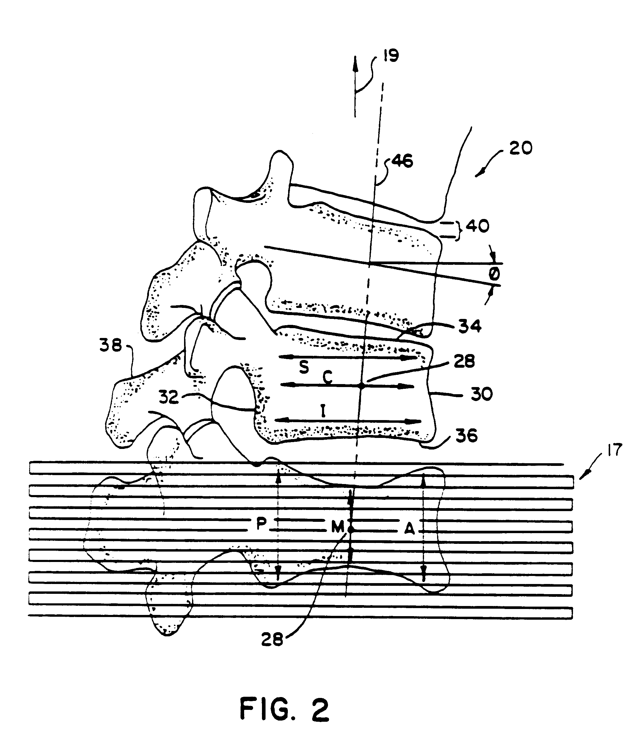
Another indicia of interest is the measurement of posterior height P of the vertebra. Like anterior height, posterior height measurements made in the prior art are taken at a single location within 5 to 10 mm of the posterior border of the vertebra. The present invention provides an automatic measurement of the average height of the posterior region of the vertebra 20 lying within the posterior fiducial zone 112 which occupies the posterior 1 / 4 of the analysis rectangle 110. Like anterior height, posterior height may be displayed to an operator in absolute units of measurement, such as millimeters, or the computer can provide height relative to the average height either of normal values of vertebrae in the general population or the other vertebrae of that patient.

example 3

Anterior / Posterior Height Comparison

An important indicia which the computer can be programmed to automatically obtain is a comparison of anterior height A to posterior height P. Typically a 15% decrease in anterior vertebral height, either relative to a norm, relative to the same individual in previous measurements, or relative to the posterior height of the same vertebra, is taken as an index of anterior vertebral fracture, a clinically significant indication.

example 4

Wedge Angle

Another indicia of vertebral morphology which can be automatically obtained with the present invention is the wedge angle. The wedge angle of the vertebra is defined as the degree of departure from a parallel relationship that linear extensions of the planes of averages of the inferior and superior borders would create. In the prior art, this is calculated based on the overall anterior and posterior height of the vertebra. From these values of anterior and posterior height and from the distance between the locations at which the measurements were taken, it becomes possible to calculate the angle between hypothetical straight lines extending through the superior and inferior borders of the vertebra. In the present invention, the distance between A and P for purposes of plotting the wedge angle is C. Since A, P and C are average values, variability in the wedge angle due to variation in the selection of the location for height and width measurement is avoided. Typically a 1...


PUM


Abstract

A dual energy scanning densitometry system for imaging and measuring bone density maintains acceptable flux by adjusting the x-ray current or scan speed according to preceding scan line data. The amount of acceptable flux is maintained within limits modified by information about the region of the body being scanned so that different precisions may be maintained for different body regions. Scan speed and current may be controlled so that scan speed is maximized within the current limits. Essentially continuous flux control can be achieved.

Description

BACKGROUND OF THE INVENTIONThe present invention relates to dual energy x-ray imaging and measuring equipment that distinguish between multiple basis materials. Particularly, the invention is a scanning bone densitometry system that adjusts x-ray flux by varying the current level of the x-ray source.The measurement of x-ray energy attenuated by an object in two distinct energy bands can be used to determine information about the materials of the imaged object. Generally attenuation is a function of x-ray energy according to two attenuation mechanisms of photoelectric absorption and Compton scattering. These two mechanisms differ among materials of different atomic numbers. For this reason, measurements at two energies can be used to distinguish between two different basis materials. Dual energy x-ray techniques can be used to separate bony tissue from soft tissue in medical imaging and quantitative bone density measuring.In such dual energy measurements, the spectral characteristics...

Claims


Application Information

Patent Timeline
IPC IPC(8): A61B6/00G01V5/00G01T1/00G01T1/163G06T7/60G06T7/00A61F2/32A61F2/00A61F2/28A61F2/44A61F2/36A61B6/03
CPCA61B6/405A61B6/4241A61B6/482A61B6/505G01T1/163G01V5/0041G06T7/0012G06T7/60A61B6/4035A61F2/28A61F2/32A61F2/367A61F2/3676A61F2/44A61F2002/3008A61F2250/0098A61F2310/00011A61F2310/00179G06T2207/30012G06T2207/30172
Inventor MAZESS, RICHARD B.ERGUN, DAVID L.
Owner LUNAR CORP
Why Eureka
Try Eureka