
Novel gate drive circuit and drive method

A gate drive circuit, a new type of technology, applied in the direction of electrical digital data processing, instruments, data processing input/output process, etc., can solve the problem of insufficient Q point voltage, insufficient gate output waveform voltage level, and Q point voltage leakage. Eliminate problems such as dropouts, achieve the effects of improving horizontal stripes, good display effects, and short leakage time

Active Publication Date: 2021-12-10
FUJIAN HUAJIACAI CO LTD
View PDF9 Cites 0 Cited by
  • Summary
  • Abstract
  • Description
  • Claims
  • Application Information

AI Technical Summary

Problems solved by technology

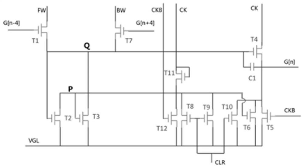
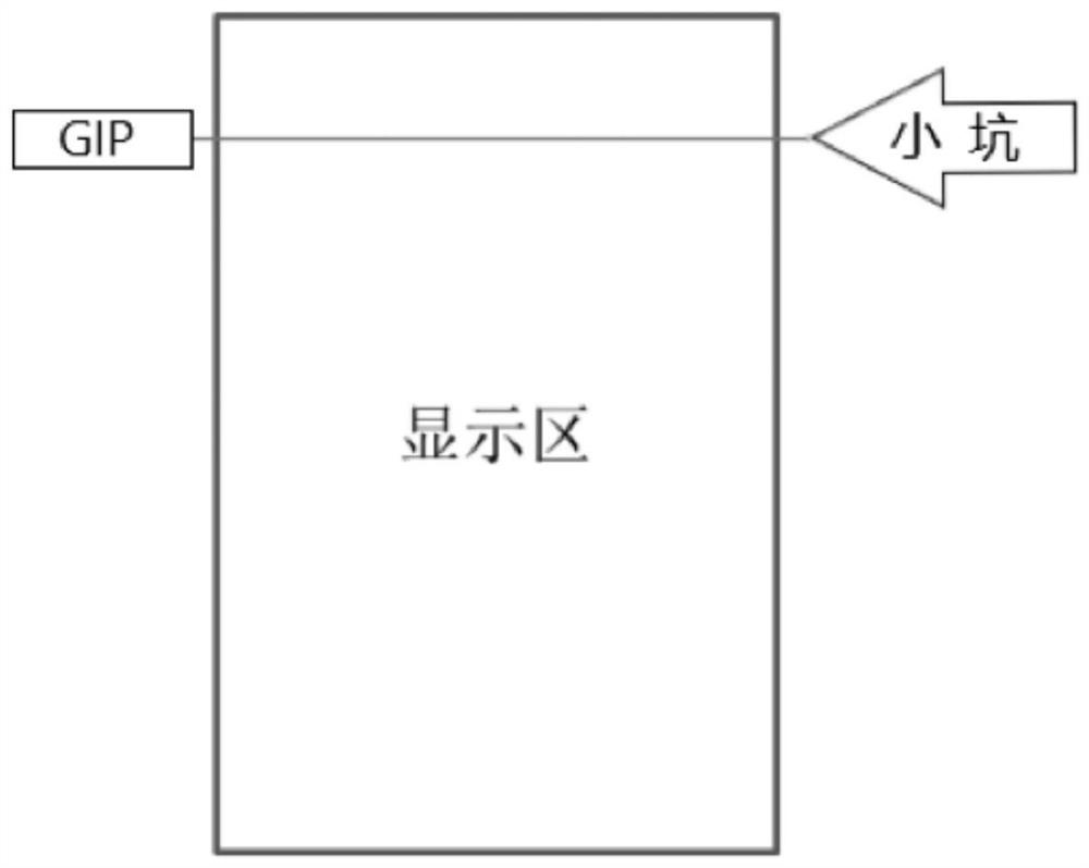
[0004] In the gate drive circuit in the prior art, such as figure 1 As shown, when the LongH touch mode is used, if the touch detection is entered, the touch mode will be entered in some row gate drive circuits, and the display related CK / CKB and other signals need to enter low potential, such as figure 2 As shown, it enters the small pit position. At this time, the Q of these gate drive circuits is still maintained at the VGH level, but because the small pit time, that is, the time for the Q point to maintain VGH, is much longer than the time for the Q point to maintain the normal display. However, in practice, the voltage at point Q will leak due to the leakage of thin film transistors, such as figure 1 As shown, it will leak electricity through devices such as T7 and T3, which will lead to insufficient voltage at point Q. Therefore, when the touch detection time changes to display time, that is, when a small pit occurs, when point Q needs to be boosted again, However, due to leakage, the voltage at point Q is never insufficient, which affects the opening of T4, resulting in insufficient voltage level of the gate output waveform, which in turn affects the charging of pixels, resulting in horizontal stripes on the display, such as image 3 shown

Method used


Image

  • Novel gate drive circuit and drive method
  • Novel gate drive circuit and drive method
  • Novel gate drive circuit and drive method

Examples


Embodiment Construction

[0042] The following will clearly and completely describe the technical solutions in the embodiments of the present invention with reference to the accompanying drawings in the embodiments of the present invention. Obviously, the described embodiments are only some, not all, embodiments of the present invention. Based on the embodiments of the present invention, all other embodiments obtained by persons of ordinary skill in the art without making creative efforts belong to the protection scope of the present invention.

[0043] see Figure 4-6 , the present invention provides a technical solution: a novel gate drive circuit, including a first switching element T1, a second switching element T2, a third switching element T3, a fourth switching element T4, a fifth switching element T5, a sixth switching element The switching element T6, the seventh switching element T7, the eighth switching element T8, the ninth switching element T9, the tenth switching element T10, the eleventh...


PUM


Abstract

The invention relates to the technical field of gate drive circuits, in particular to a novel gate drive circuit and a drive method. The novel gate drive circuit comprises a first switch element, a second switch element, a third switch element, a fourth switch element, a fifth switch element, a sixth switch element, a seventh switch element, an eighth switch element, a ninth switch element, a tenth switch element, an eleventh switch element, a twelfth switch element and a thirteenth switch element. The first switch element comprises a first access end, a second access end and a first control end, the first access end is connected with a forward signal, the second access end is connected with a current-stage gate driving signal, and the first control end is connected with previous four-stage gate driving signals. According to the invention, a novel gate drive circuit design is adopted, the cross grain phenomenon in a LongH mode can be improved, and a better display effect can be obtained.

Description

technical field [0001] The invention relates to the technical field of gate drive circuits, in particular to a novel gate drive circuit and a drive method. Background technique [0002] With the development and progress of the society, people's demand for display device experience is further improved. Therefore, compared with the traditional external display touch module, the embedded display touch module can reduce the module cost and reduce the module cost. Group thickness, improved module brightness, and better touch accuracy have gradually entered the public's field of vision and gained people's favor. In terms of drive, the touch mode of the embedded display touch module can be divided into LongV mode and LongH mode. In the former mode, the touch detection is performed after the display is completed within one frame, and the timing control of the display and touch does not interfere. Compared with the former, the latter has a Better touch reporting rate to achieve more...

Claims


Application Information

Patent Timeline
Patent Type & Authority Applications(China)
IPC IPC(8): G09G3/20G06F3/041
CPCG09G3/20G06F3/0412
Inventor 祝海龙吕陈凤吴文靖林剑锋
Owner FUJIAN HUAJIACAI CO LTD
Learn More