Intelligent fly trap cage device

A smart, cage-based technology, applied in the field of vector monitoring, can solve the problems of increasing workload and labor force, and being unable to know the situation in the cage in time, so as to reduce the workload.

Pending Publication Date: 2021-12-14
福建优信物联科技有限公司 +1
View PDF0 Cites 0 Cited by
  • Summary
  • Abstract
  • Description
  • Claims
  • Application Information

AI Technical Summary

Problems solved by technology

At present, the common fly trapping device on the market is a simple fly trap device. The existing fly trapping device adopts the traditional trapping method. Workload and Labor

Method used


Image

  • Intelligent fly trap cage device

Examples


Embodiment approach

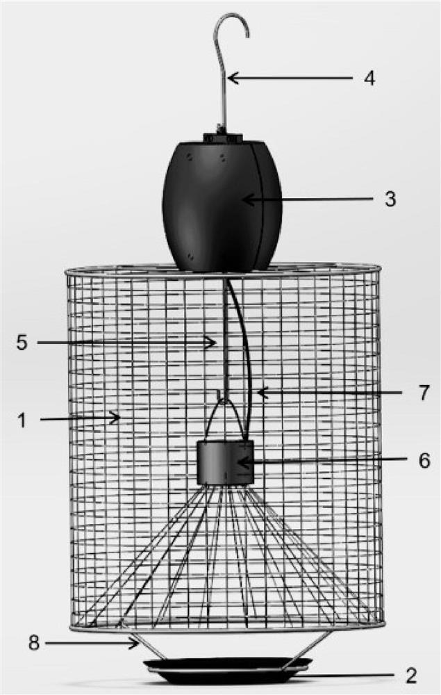
[0020] As a further embodiment of the present invention: the waterproof box 3 is cylindrical, and the waterproof box 3 is fixedly installed with a control board and a power supply. The control board adopts a low-power MCU, and the control board includes a temperature and humidity sensor module and a wireless communication module. When working, the control board uses a low-power MCU, so that the battery life of the device can be extended to more than 1 year. At the same time, the temperature and humidity sensor module can monitor the temperature and humidity data of the deployment environment, and the wireless communication module can collect and transmit the data collected by the sensor. .

[0021] As a further embodiment of the present invention: the control main board is connected with the infrared laser shooting sensor module by the electronic connection line 7. During work, the control main board is connected with the infrared laser shooting sensor module by the electronic ...


PUM


Abstract

The invention discloses an intelligent fly catching cage device in the field of vector monitoring. The intelligent fly catching cage device comprises a cage body, wherein a waterproof box is fixedly connected to the upper end of the cage body, a first hook is fixedly connected to the upper end of the waterproof box, and a second hook and an access channel are fixedly connected into the cage body; the lower end of the cage body is fixedly connected with a bait box support, and a bait box is placed in the bait box support. The structure is simple, the manufacturing cost is low, and the workload of workers can be reduced only through simple operation.

Description

technical field [0001] The invention relates to the field of vector monitoring, in particular to an intelligent fly trap device. Background technique [0002] With the advent of the high temperature season in summer, vector organisms such as flies have also begun to breed in large numbers. Local customs carried out vector monitoring and prevention and control work in accordance with the guidelines of the General Administration. At present, the common fly trapping device on the market is a simple fly trap device. The existing fly trapping device adopts the traditional trapping method. Workload and labor. [0003] Therefore, the present invention provides a smart fly trap device to solve the problems raised in the above-mentioned background technology. Contents of the invention [0004] The purpose of the present invention is to provide an intelligent fly trap device to solve the problems raised in the above-mentioned background technology. [0005] To achieve the above ...

Claims


Application Information

Patent Timeline
Patent Type & Authority Applications(China)
IPC IPC(8): A01M1/02A01M1/10G06M1/272
CPCA01M1/02A01M1/106G06M1/272A01M2200/012
Inventor 林雨高博张建庆黄恩炯朱友训黄志仁吴学钦
Owner 福建优信物联科技有限公司
Why Eureka
Try Eureka