Transfer robot
A technology of handling robots and mounting plates, applied in the field of handling robots, can solve the problems of high minimum pickup height and the inability of handling robots to pick up and place goods, and achieve the effect of increasing the scope of pickup
- Summary
- Abstract
- Description
- Claims
- Application Information
AI Technical Summary
Problems solved by technology
Method used
Image
Examples
Embodiment 1
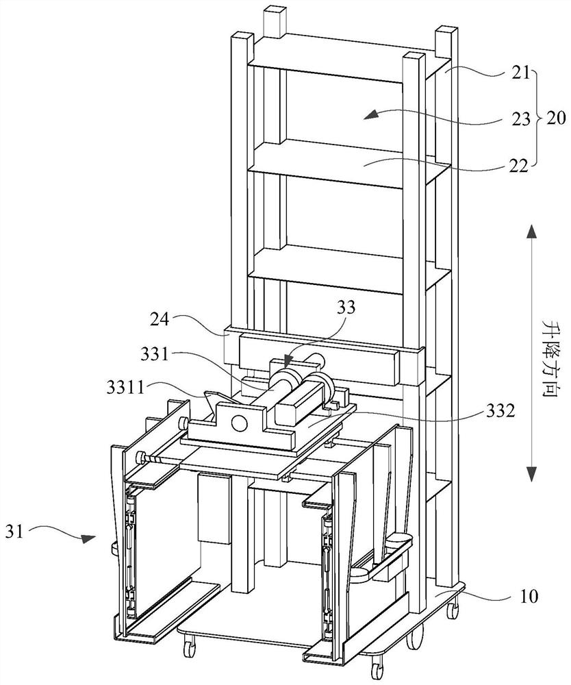
[0067] figure 1 It is a structural schematic diagram of a handling robot provided by an embodiment of the present disclosure; Figure 4 Yes figure 1 Structural schematic diagram of the handling device of the medium handling robot; Figure 5 Yes Figure 4 The front view of the medium handling device; Figure 7 Yes Figure 4 Schematic diagram of the structure of the medium handling device after removing the first mounting plate.
[0068] refer to figure 1 , Figure 4 , Figure 5 and Figure 7 An embodiment of the present disclosure provides a handling robot, including a mobile chassis 10 , a shelf 20 and a handling device 30 , the shelf 20 is set on the mobile chassis 10 , and the handling device 30 is set on the shelf 20 .
[0069] Wherein, the bottom of the mobile chassis 10 can be provided with a plurality of rollers, exemplary, the rollers can be universal wheels, the rollers can drive the mobile chassis 10 to move, the inside of the mobile chassis 10 can also be pr...
Embodiment 2
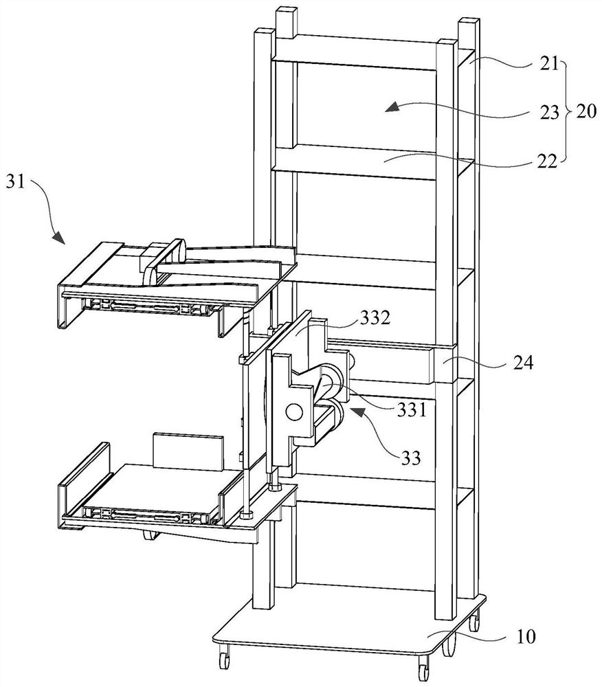
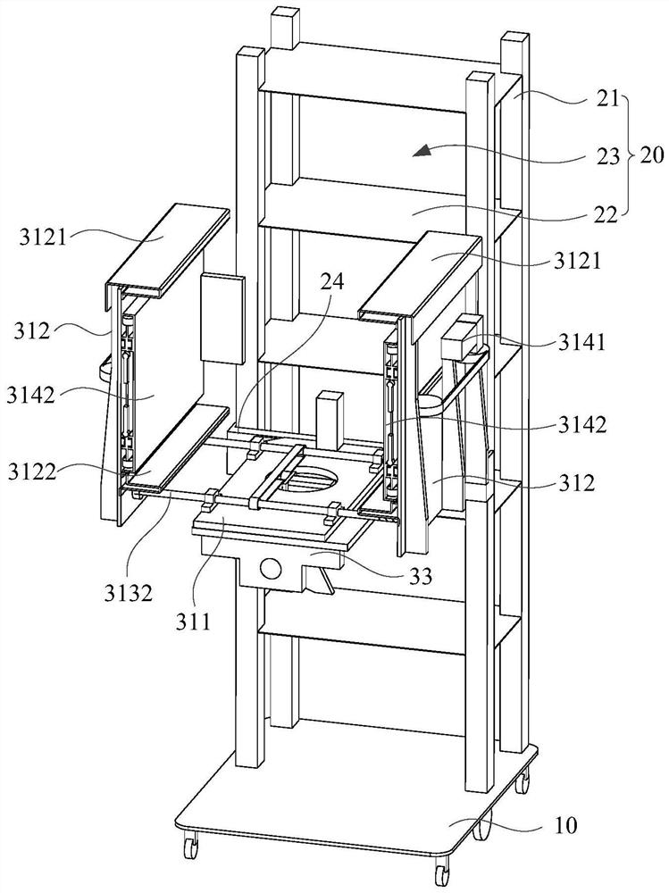
[0091] figure 2 Yes figure 1 Schematic diagram of the structure of the first fork assembly of the middle handling robot rotated by 90°; image 3 Yes figure 1 Schematic diagram of the structure of the first fork assembly of the middle handling robot rotated by 180°; Image 6 Yes Figure 4 Schematic diagram of the structure of another viewing angle of the medium handling device.
[0092] refer to Figure 1 to Figure 7 , on the basis of Embodiment 1, this embodiment of the present disclosure provides a handling robot, the connecting base 33 of the handling robot includes a fixed part 331 and a rotating part 332, the first end of the fixed part 331 is connected to the shelf 20 On one side, the second end of the fixing portion 331 extends in a direction away from the shelf 20 along the horizontal direction. The rotating part 332 is rotatably sleeved on the second end of the fixing part 331 , and the rotating part 332 rotates around the fixing part 331 in a vertical plane. E...
Embodiment 3
[0111] Figure 8 It is a schematic structural diagram of another handling robot provided by an embodiment of the present disclosure; Figure 9 Yes Figure 8 The side view of the handling robot in the middle; Figure 10 Yes Figure 8 Schematic diagram of the structure of the first viewing angle of the handling device of the medium handling robot; Figure 11 Yes Figure 10 Schematic diagram of the structure of the second viewing angle of the medium handling device; Figure 12 Yes Figure 10 The front view of the medium handling device; Figure 13 Yes Figure 10 Schematic diagram of the structure of the medium handling device after removing the second mounting plate; Figure 14 Yes Figure 10 Enlarged image at A.
[0112] refer to Figure 8 to Figure 14 , on the basis of Embodiment 1, the present disclosure provides a handling robot, the handling device 30 of the handling robot further includes a second fork assembly 32, and the second fork assembly 32 includes a secon...
PUM
| Property | Measurement | Unit |
|---|---|---|
| Rotation range | aaaaa | aaaaa |
Abstract
Description
Claims
Application Information
 - R&D
- Intellectual Property
- Life Sciences
- Materials
- Tech Scout
- Unparalleled Data Quality
- Higher Quality Content
- 60% Fewer Hallucinations
Browse by: Latest US Patents, China's latest patents, Technical Efficacy Thesaurus, Application Domain, Technology Topic, Popular Technical Reports.
© 2025 PatSnap. All rights reserved.Legal|Privacy policy|Modern Slavery Act Transparency Statement|Sitemap|About US| Contact US: help@patsnap.com


