Detonator demolding and bundling equipment and detonator demolding and bundling method

A detonator and demoulding technology, which is applied in the direction of detonators, offensive equipment, strapping machine parts, etc., can solve the problems of low production efficiency, labor and time-consuming, etc.

Pending Publication Date: 2021-12-14
深圳市锐巽自动化设备有限公司
View PDF0 Cites 1 Cited by
  • Summary
  • Abstract
  • Description
  • Claims
  • Application Information

AI Technical Summary

Problems solved by technology

After the detonator is assembled, it needs to be separated from the jig. This process is called demoulding. After demoulding, the main body of the detonator and the wire clips at both ends of the wire must be stored on the side of the coiled wire. Then bundle multiple detonators and pack them. At present, the demoulding and bundling of the detonators are all done manually, which is labor-intensive and time-consuming, and the production efficiency is low.

Method used


Image

  • Detonator demolding and bundling equipment and detonator demolding and bundling method
  • Detonator demolding and bundling equipment and detonator demolding and bundling method
  • Detonator demolding and bundling equipment and detonator demolding and bundling method

Examples


Embodiment Construction

[0048] Embodiments of the present application are described in detail below, examples of which are shown in the drawings, wherein the same or similar reference numerals denote the same or similar elements or elements having the same or similar functions throughout. The embodiments described below by referring to the figures are exemplary, and are only for explaining the present application, and should not be construed as limiting the present application.

[0049] In the description of the present application, it should be understood that the orientation descriptions, such as up, down, front, back, left, right, etc. indicated orientations or positional relationships are based on the orientations or positional relationships shown in the drawings, and are only In order to facilitate the description of the present application and simplify the description, it does not indicate or imply that the device or element referred to must have a specific orientation, be constructed and operat...


PUM


Abstract

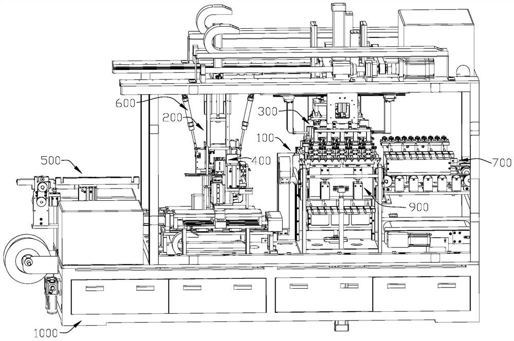
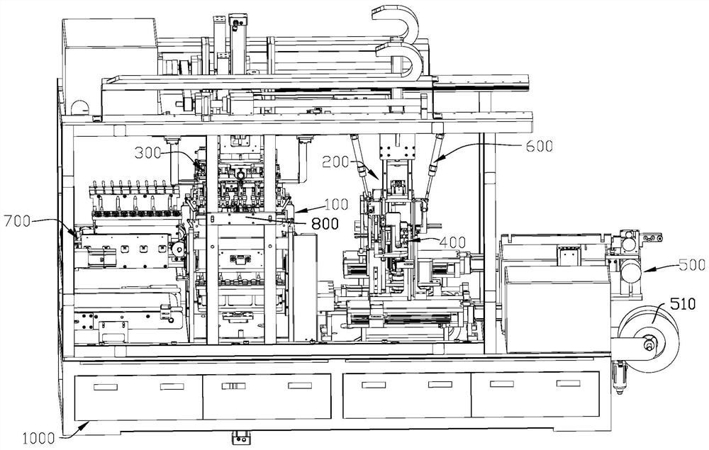
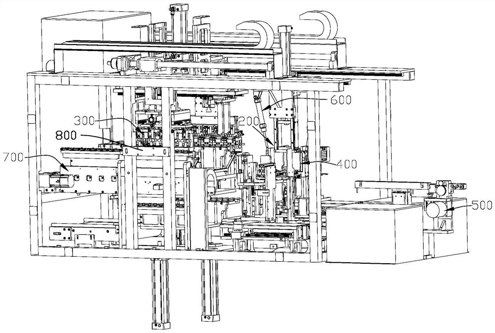
The invention discloses detonator demolding and bundling equipment and method. A jig is placed on a demolding station, detonators are placed on the jigs, a detonator grabbing device grabs the detonators from the jig on the demolding station and conveys the detonators to a bundling station, and a turnover device receives the detonators conveyed by the detonator grabbing device, turnovers the main bodies of the detonators towards the leg wire direction of the detonators, and overturn the wire clips of the detonators towards the leg wire direction; and a binding device grabs a bundling wire on a bundling wire conveying device and drives the bundling wire to bundle the detonators. Separation of the detonators from the jig is completed, and the detonators are bundled. Compared with manual demolding and bundling, the detonator demolding and bundling equipment and method provided by the embodiment of the invention have the advantages that the production efficiency can be improved, and the labor force can be saved.

Description

technical field [0001] The application relates to the technical field of blasting equipment production, and in particular to a detonator stripping and binding device and a detonator stripping and binding method. Background technique [0002] The electronic detonator is a kind of detonator that explodes due to the action of electric energy. Compared with the fire detonator, the electronic detonator has the functions of detonation delay time control and detonation energy control. The electrical performance of the components is tested, and it can be remotely ignited and a large number of explosives can be detonated at one time. It is safe to use and high in efficiency, and is widely used in blasting operations. [0003] The detonator mainly includes three parts: the main body of the detonator, the foot wire and the wire clip. The wire is coiled into a bundle, one end of the wire is connected to the plug of the main body of the detonator, and the other end of the wire is install...

Claims


Application Information

Patent Timeline
IPC IPC(8): C06C7/02B65B13/18B65B35/16B65B35/58
CPCC06C7/02B65B13/18B65B35/16B65B35/58
Inventor 吴云松
Owner 深圳市锐巽自动化设备有限公司
Why Eureka
Try Eureka