Sliding type photovoltaic panel surface automatic cleaning device

An automatic cleaning, photovoltaic panel technology, applied in photovoltaic modules, photovoltaic power generation, cleaning flexible items and other directions, can solve the problems of high labor cost, reduced cleaning effect, reduced power generation per unit land area, etc., to reduce energy and resource consumption, The effect of reducing the consumption of human resources and avoiding the reduction of power generation efficiency

Inactive Publication Date: 2021-12-14
陈树强
View PDF0 Cites 0 Cited by
  • Summary
  • Abstract
  • Description
  • Claims
  • Application Information

AI Technical Summary

Problems solved by technology

[0004] In order to overcome the problems of photovoltaic panel cleaning technologies, there are mainly manual cleaning and semi-automatic cleaning, among which manual cleaning is mostly for workers to wash or scrub the surface of photovoltaic panels with hand-held cleaning devices. This method requires a lot of human resources. Therefore, the labor cost is too high and the efficiency is low. There are two types of semi-automatic cleaning. One is to install a mechanical arm and a cleaning device behind the vehicle to rinse and wipe the surface of the photovoltaic panel. The cleaning device slides along the frame of the photovoltaic panel, and the cleaning mechanism installed inside it can clean the surface of the photovoltaic panel during its movement. These two devices still need to be manually operated or installed on each row of photovoltaic panels , and the former needs to reserve a passage for cleaning vehicles between each row of photovoltaic panels, so as to reduce the number of photovoltaic panels installed per uni

Method used


Image

  • Sliding type photovoltaic panel surface automatic cleaning device
  • Sliding type photovoltaic panel surface automatic cleaning device
  • Sliding type photovoltaic panel surface automatic cleaning device

Examples


Embodiment

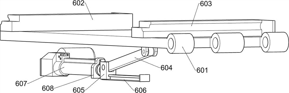
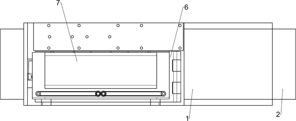
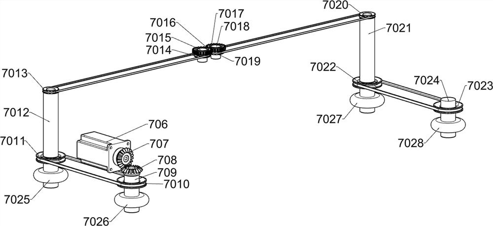
[0028] A sliding photovoltaic panel surface automatic cleaning device, such as Figure 1-3 As shown, it includes an electric slide car 1, a long slide rail frame 2, an operation control panel 3, a first support column 4, a second support column 5, an inclined plate lifting mechanism 6, a sliding cleaning mechanism 7 and an electric roller brush mechanism 8 The electric slide rail car 1 is installed above the long slide rail frame 2; the operation control panel 3 is installed on one side of the electric slide rail car 1; the first support column 4 is screwed with the upper panel of the electric slide rail car 1; 4 The upper end is in contact with the swash plate lifting mechanism 6; the second support column 5 is screwed to the upper panel of the electric slide rail car 1; the second support column 5 is in contact with the swash plate lifting mechanism 6; the swash plate lifting mechanism 6 is installed on the electric Above the slide rail car 1; the sliding cleaning mechanism ...


PUM


Abstract

The invention relates to the field of photovoltaic power generation, and especially relates to a sliding type photovoltaic panel surface automatic cleaning device. The technical problem is to provide the sliding type photovoltaic panel surface automatic cleaning device. According to the technical scheme, the sliding type photovoltaic panel surface automatic cleaning device comprises an electric sliding rail vehicle, a long sliding rail frame, an inclined plate lifting mechanism, a sliding cleaning mechanism and an electric rolling brush mechanism; and the electric slide rail vehicle is mounted above the long sliding rail frame. Full-automatic cleaning of a large number of photovoltaic panels is achieved, the problem that the power generation efficiency of a unit land area is reduced due to the fact that the distance between every two rows of photovoltaic panels is too large is solved, meanwhile, the risk that the photovoltaic panels are damaged is reduced, the photovoltaic panels can be rapidly and automatically replaced to another row of photovoltaic panels after a single row of photovoltaic panels is cleaned, and meanwhile, the device has the effect of using different cleaning methods for various pollutants.

Description

technical field [0001] The invention relates to the field of photovoltaic power generation, in particular to a sliding type photovoltaic panel surface automatic cleaning device. Background technique [0002] At present, the existing cleaning technologies for photovoltaic panels mainly include manual cleaning and semi-automatic cleaning. Among them, manual cleaning is mostly for workers to wash or scrub the surface of photovoltaic panels with hand-held cleaning devices. This method requires a lot of human resources. There are few people in the northwest desert area, so the labor cost is too high and the efficiency is low. There are two types of semi-automatic cleaning. One is to install a mechanical arm and a cleaning device behind the vehicle to rinse and wipe the surface of the photovoltaic panel. It is a cleaning device that can slide along the frame of the photovoltaic panel. The cleaning mechanism installed inside it can clean the surface of the photovoltaic panel during...

Claims


Application Information

Patent Timeline
IPC IPC(8): H02S40/10B08B1/00B08B1/04B08B3/02B08B11/04B08B13/00F26B5/14
CPCH02S40/10B08B1/002B08B1/04B08B3/024B08B11/04B08B13/00F26B5/14Y02E10/50
Inventor 陈树强
Owner 陈树强
Why Eureka
Try Eureka