
Tricuspid valve clamping device

A clamping device and tricuspid valve technology, applied in the field of medical devices, can solve the problems of unrealized application, difficult healing, and many complications, and achieve the effect of avoiding the phenomenon of tricuspid regurgitation

Pending Publication Date: 2021-12-21
KOKA NANTONG LIFESCIENCES CO LTD
View PDF0 Cites 0 Cited by
  • Summary
  • Abstract
  • Description
  • Claims
  • Application Information

AI Technical Summary

Problems solved by technology

[0004] Surgical valve replacement or repair is still the first choice for patients with tricuspid regurgitation, but for patients with advanced age, history of open chest, poor heart function and multiple organ insufficiency, surgical trauma is large, healing is difficult, and complications are many , the risk is high, and even some patients cannot tolerate it
[0005] At present, several products for minimally invasive transcatheter treatment of tricuspid regurgitation have been used clinically, but they are all in the experimental stage and have not yet achieved mature application, and their respective technologies have limitations

Method used


Image

  • Tricuspid valve clamping device
  • Tricuspid valve clamping device
  • Tricuspid valve clamping device

Examples


Embodiment Construction

[0048] In order to make the technical means, creative features, goals and effects achieved by the present invention easy to understand, the present invention will be further described below in conjunction with specific diagrams.

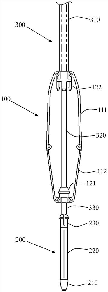
[0049] refer to Figure 1 to Figure 6 , a tricuspid valve clamping device, comprising a clamping mechanism 100 , a grasping mechanism 200 and an action mechanism 300 .

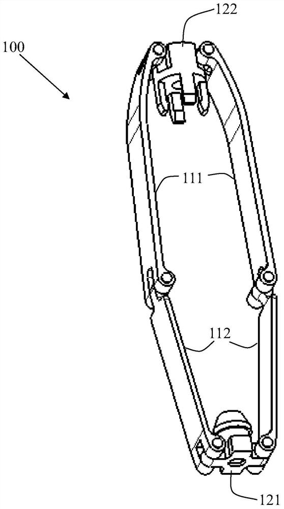
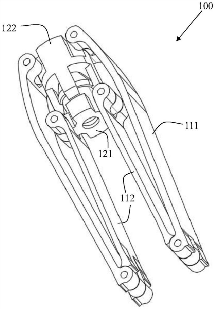
[0050] refer to Figure 2 to Figure 4 , the clamping mechanism 100 includes a clamping portion and a locking portion. Wherein, the locking part has a locking part 121 and a snapping part 122 that cooperate with each other, and the locking part 121 and the snapping part 122 are detachably connected, preferably by snap connection. The engaging part 122 is arranged at the proximal end of the clamping part, and the locking part 121 is arranged at the far end of the clamping part.

[0051] The clamping part can be an elastic ring body, and the two inner walls of the elastic ring body r...


PUM


Abstract

The invention belongs to the technical field of medical instruments, and particularly relates to a tricuspid valve clamping device. The tricuspid valve clamping device comprises a clamping mechanism, a grabbing mechanism and an action mechanism, wherein the clamping mechanism comprises a clamping part and a locking part which is provided with a locking piece and a clamping piece which are matched with each other and are respectively arranged on two sides of the clamping part; the grabbing mechanism comprises a pushing head and a retarding component, wherein the far end of the retarding component is connected with the pushing head; and the action mechanism drives the locking piece to be close to or away from the clamping piece and drives the pushing head and the retarding component to be close to or away from the clamping part. On the basis that original valve leaflets are kept as much as possible, the tricuspid valve is annularly shrunk, the valve leaflets are completely closed when the heart is shrunk, and the tricuspid valve regurgitation phenomenon is reduced or avoided.

Description

technical field [0001] The invention belongs to the technical field of medical devices, and in particular relates to a tricuspid valve clamping device. Background technique [0002] The tricuspid valve is located at the mouth of the right atrium, and the common occurrence is tricuspid regurgitation, that is, blood flow from the right ventricle flows back into the right atrium during systole, resulting in a highly enlarged right atrium, increased pressure, and venous blood return obstruction. Due to the increased right ventricular load, compensatory hypertrophy, prone to right heart failure. [0003] Tricuspid regurgitation is generally caused by pulmonary hypertension, right ventricle enlargement, and tricuspid annulus expansion. Clinically, the etiology of tricuspid regurgitation (left heart failure, pulmonary hypertension, etc.) After valve regurgitation, symptoms of right heart failure such as fatigue, ascites, edema, pain in the liver area, indigestion, and anorexia agg...

Claims


Application Information

Patent Timeline
IPC IPC(8): A61F2/24
CPCA61F2/246A61F2/2466
Inventor 吴明明耿肖肖陈大凯
Owner KOKA NANTONG LIFESCIENCES CO LTD
Learn More