Medical leg muscle rehabilitation equipment

A kind of rehabilitation equipment and muscle technology, applied in the direction of muscle training equipment, physical therapy, gymnastics equipment, etc., can solve problems such as single function, and achieve the effect of avoiding secondary injury

Active Publication Date: 2021-12-21
滨州医学院附属医院
View PDF5 Cites 1 Cited by
  • Summary
  • Abstract
  • Description
  • Claims
  • Application Information

AI Technical Summary

Problems solved by technology

[0004] In order to overcome the single function of existing rehabilitation training equipment, the lack of blood circulation to the feet before training and the shortcomings of massaging the feet after training, the technical problem is: to provide a device that can activate blood circulation to the feet before training and can massage the feet after training. Medical leg muscle rehabilitation equipment for massaging the feet

Method used


Image

  • Medical leg muscle rehabilitation equipment
  • Medical leg muscle rehabilitation equipment
  • Medical leg muscle rehabilitation equipment

Examples


Embodiment 1

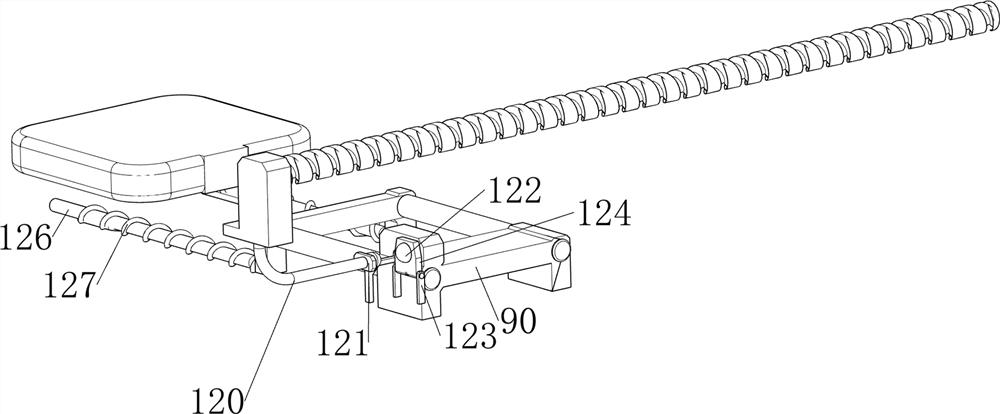
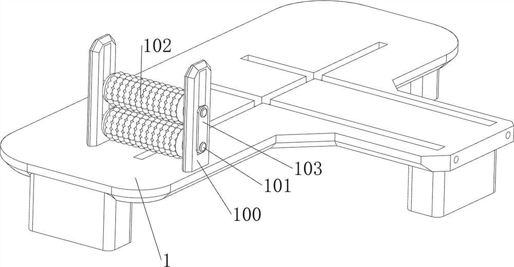
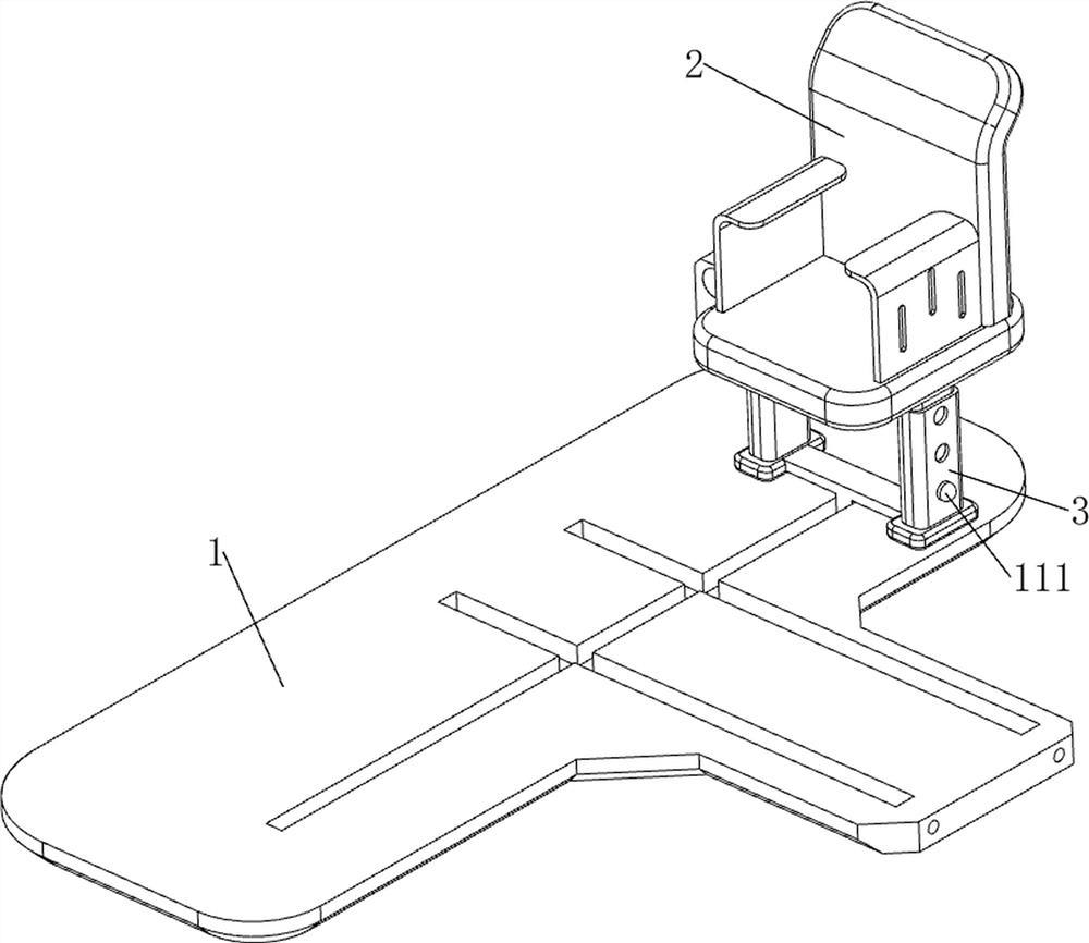
[0065] A medical leg muscle rehabilitation device, such as figure 1 , figure 2 , Figure 4 , Figure 5 , Figure 6 and Figure 7 Shown, include bottom plate 1, back board 2, first support column 3, first connecting plate 4, movable block 5, first movable bar 6, first spring 7, pedal mechanism 9, foot lifting mechanism 10 and telescopic Mechanism 11, the upper rear side of the base plate 1 is slidingly provided with a first support column 3, and the first support column 3 is provided with a telescopic mechanism 11, and the telescopic mechanism 11 is provided with a backboard 2, and the left and right sides of the front side of the bottom of the backboard 2 Both are provided with the first connecting plate 4, and the top of the first connecting plate 4 is provided with two first movable rods 6, and movable blocks 5 are slidingly arranged between the first movable rods 6 on the same side. 5. There are two first springs 7 between the top and the inner top of the first connec...

Embodiment 2

[0071] On the basis of Example 1, such as figure 1 , image 3 , Figure 8 , Figure 9 , Figure 10 and Figure 11 As shown, a moving mechanism 8 is also included, and the moving mechanism 8 includes a second support column 80, a screw mandrel 81, a hand lever 82 and a first movable plate 83, and the front and rear sides on the left side of the bottom plate 1 are provided with second supports. Column 80, the rotation type is provided with screw mandrel 81 between the second support column 80 tops, and the rear side of screw mandrel 81 is provided with hand bar 82, and first support column 3 left upper part is provided with first movable plate 83, and first movable plate 83 left parts are threadedly connected with screw mandrel 81 rear sides.

[0072] When people need to push the backrest board 2 to move back and forth, they can turn the hand lever 82 forward and reverse, so that the hand lever 82 drives the screw rod 81 to rotate forward and reverse, thereby driving the fi...


PUM


Abstract

The invention relates to rehabilitation equipment, in particular to medical leg muscle rehabilitation equipment. The technical problem is to provide the medical leg muscle rehabilitation equipment capable of activating blood of feet before training and massaging the feet after training. The medical leg muscle rehabilitation equipment comprises: a bottom plate and a first supporting column, wherein the first supporting column is arranged on one side of the upper portion of the bottom plate in a sliding mode; a telescopic mechanism, wherein the telescopic mechanism is arranged on the first supporting column; a backrest plate, wherein the backrest plate is arranged on the telescopic mechanism; first connecting plates, wherein the first connecting plates are arranged on the two sides of one side of the bottom of the backrest plate; and first movable rods, wherein the two first movable rods are arranged at the inner top of each of the first connecting plates. Through cooperation of the backrest plate, the foot lifting mechanism and the telescopic mechanism, people can conveniently activate blood of feet before training and massage the feet after training, cramp of the feet and legs after training is prevented, and secondary injury is avoided.

Description

technical field [0001] The invention relates to a rehabilitation device, in particular to a medical leg muscle rehabilitation device. Background technique [0002] Some patients with leg injuries often need a series of rehabilitation training after rehabilitation. However, due to the lack of training equipment, simple walking training can only be performed indoors or outdoors, and it must be performed under the care of nursing staff, so it is easy Secondary injuries caused by collisions, and rehabilitation training cannot be carried out at any time, so most patients will use rehabilitation training equipment, and can perform training according to their own needs without bothering others. [0003] Because most of the existing rehabilitation training equipment has a single function, people basically do leg exercises directly to train themselves when using them. Due to the lack of blood circulation on the feet before training and massage on the feet after training , causing th...

Claims


Application Information

Patent Timeline
Patent Type & Authority Applications(China)
IPC IPC(8): A63B22/04A63B23/04A63B23/10A63B21/055A61H39/04
CPCA63B22/04A63B21/055A63B23/10A63B23/04A61H39/04A61H2201/1261A61H2205/125
Inventor 谢宗春
Owner 滨州医学院附属医院
Why Eureka
Try Eureka