
Leg Garment

Active Publication Date: 2011-12-29
OKAMOTO INDS
View PDF37 Cites 42 Cited by
  • Summary
  • Abstract
  • Description
  • Claims
  • Application Information

AI Technical Summary

Benefits of technology

[0014]The present invention has been made to solve such problems, and an object of the present invention is to provide a leg garment capable of promoting blood circulation to remove swelling while preventing a wearer from having a discomfort feeling because of excessive tightness and providing a moderate pressure sensation (feeling of moderate tightness), as well as suppressing impediments for blood circulation to maintain a heat-retention effect.
[0021]Furthermore, it is preferable that: the body portion be formed so as to cover at least a part of the leg up to a lower leg; and the support strip include a fourth tightening portion arranged so as to extend obliquely upward from an external side of the lower leg to a ventral side of the lower leg to reach a ventral side of a lower end of a knee cap. Consequently, the support strip can be formed so as to avoid the part in which the great saphenous vein, the saphenous nerve and the lateral sural cutaneous nerve are superficially present, the part being located medial to the center of the body of the wearer relative to a shin bone, enabling return of venous blood and lymph to the heart to be prevented from being disturbed, as well as compressing a part of the wearer's body from a ventral side of a lower leg from a lateral side of the lower leg to promote blood circulation.

Problems solved by technology

Formation of a support strip so as to extend across such vein and nerve at the shin impede return of venous blood and thus, disturbs blood circulation, causing a problem in that swelling cannot be removed.
Where a lower leg of a wearer is compressed by an excessive circumferential force that makes the wearer find it too tight, blood circulation may be suppressed, resulting in cooling in the toes.
If a further increased circumference force is applied, the wearer may have a pain during wearing or deformation of the subcutaneous tissue at the corresponding region of the leg after wearing.
However, such high pressure value can be considered to produce excessively strong compression on the body part.

Method used


Image

  • Leg Garment
  • Leg Garment
  • Leg Garment

Examples


Embodiment Construction

[0039]Hereinafter, a preferred embodiment of the present invention will be described in details with reference to the drawings. Here, components that are identical or correspond to each other in the respective drawings are provided with a same reference numeral. In the present embodiment, a description will be given in terms of a compression sock (leg garment).

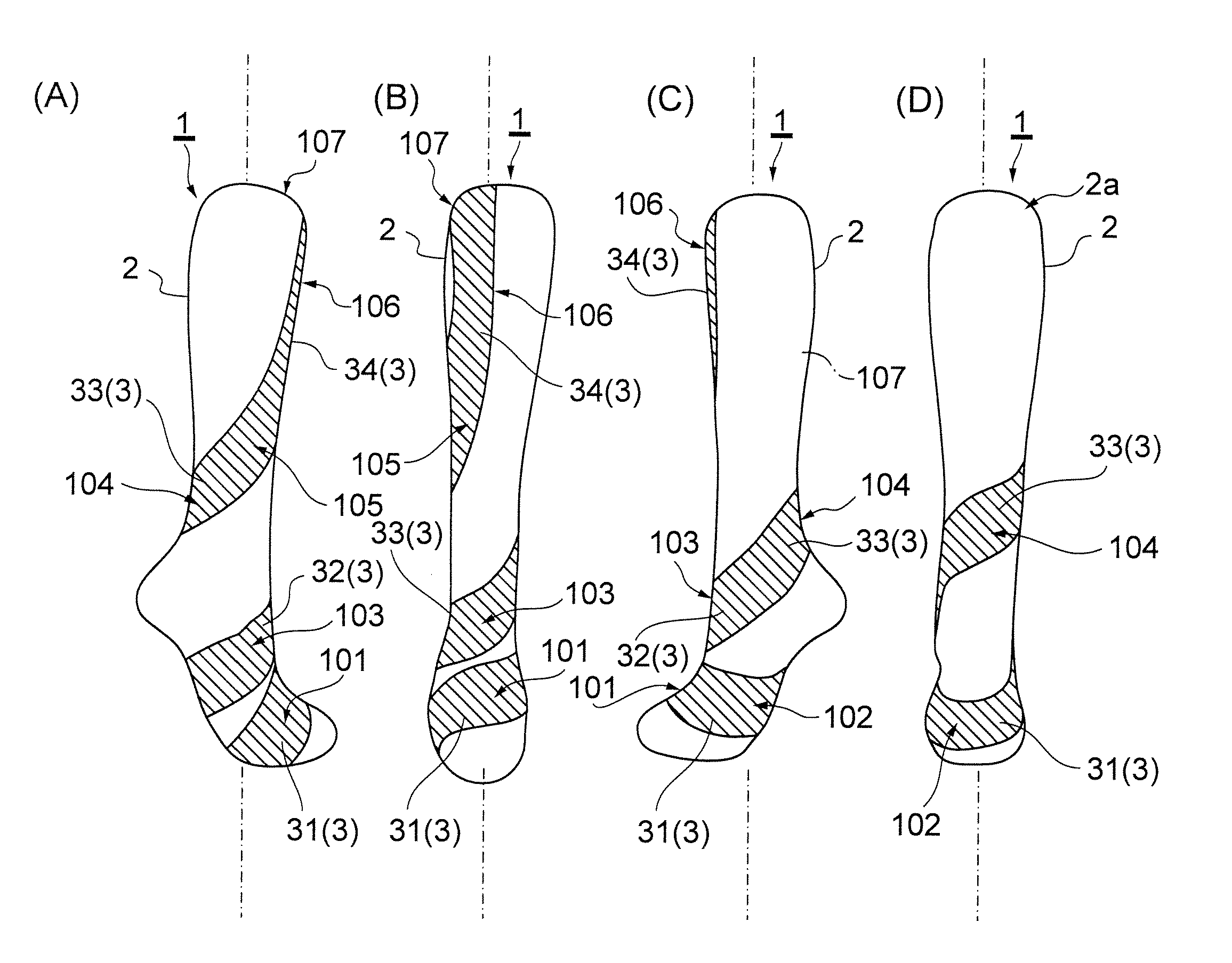
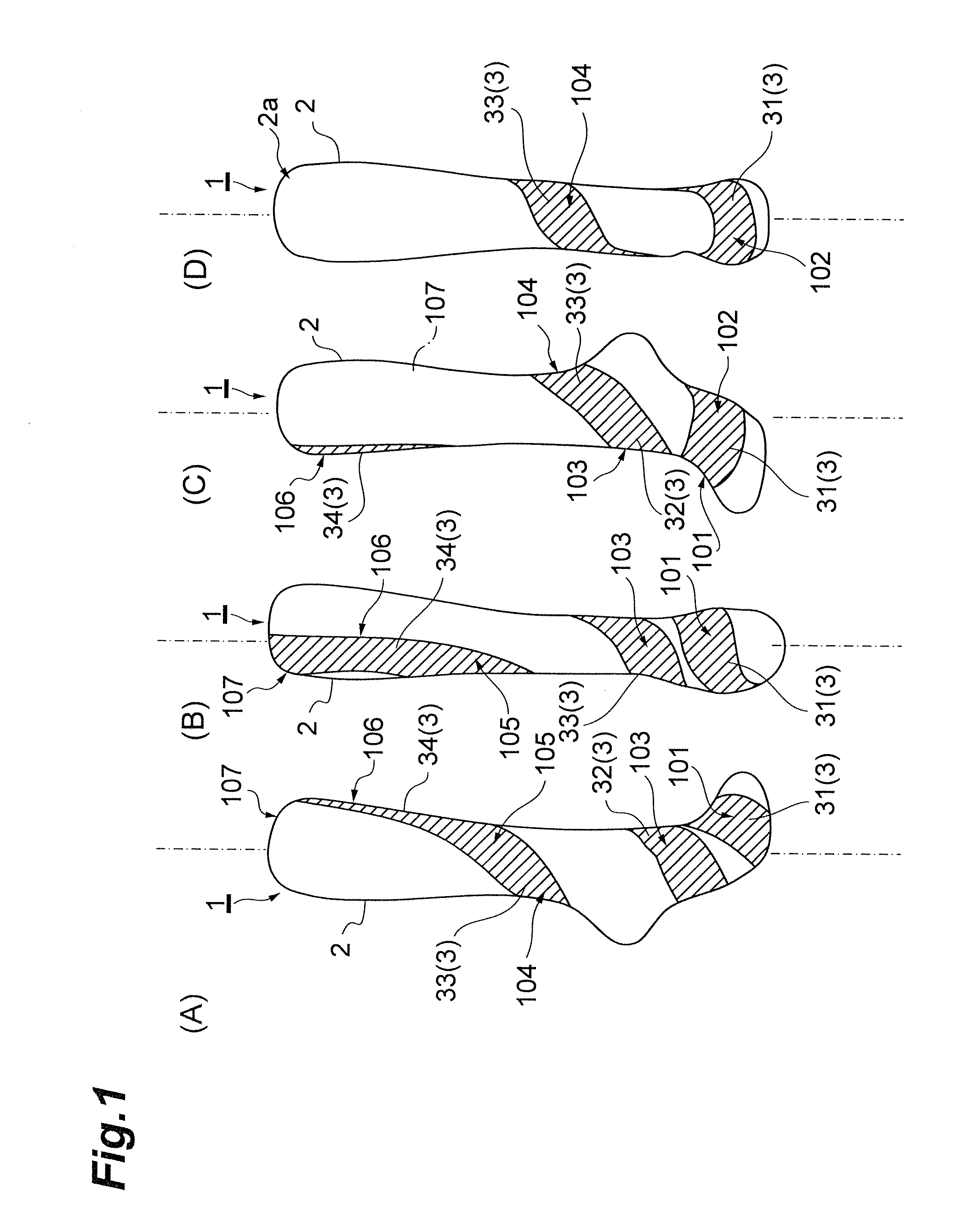
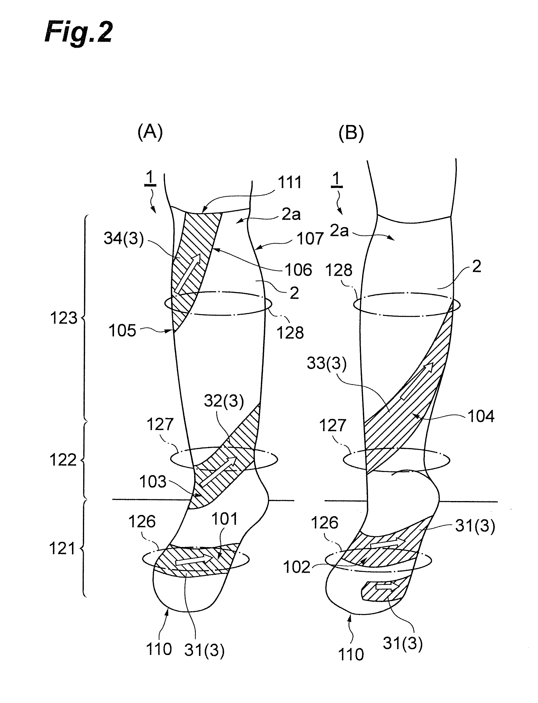
[0040]FIGS. 1(A) to 1(D) and 2(A) and 2(B) are diagrams each illustrating a compression sock (for a right leg) according to an embodiment of the present invention. FIG. 1(A) is an outer side view. FIG. 1(B) is a front view. FIG. 1(C) is an inner side view. FIG. 1(D) is a back view. Also, FIG. 2(A) is a front view. FIG. 2(B) is a back view.

[0041]The compression sock 1 (helical compression sock) illustrated in FIGS. 1(A) to 1(D) and FIGS. 2(A) and 2(B) is a sock including a support strip 3 formed in a tubular body portion 2, the support strip 3 exerting a tightening force larger than that of a part of the compression sock 1 arou...


PUM


Abstract

A leg garment according to the present invention includes a body portion covering at least an instep, a sole and an ankle of a leg. The leg garment includes a support strip exerting a tightening force larger than that of a portion of the leg garment around the support strip. The support strip is arranged in the shape of an inwardly-wound helix extending from the instep to the ankle through the sole. The support strip includes: a first tightening portion arranged so as to medially extend from the instep to the sole; and a second tightening portion arranged so as to extend obliquely upward from a lateral side to a medial side of a ventral ankle, the second tightening portion compressing the ventral ankle via a surface thereof.

Description

BACKGROUND OF THE INVENTION[0001]1. Field of the Invention[0002]The present invention relates to a leg garment including a support strip in a tubular body portion, the support strip exerting a tightening force larger than that of a portion of the leg garment around the support strip.[0003]2. Related Background Art[0004]In recent years, an increasing number of people perceive swelling of their lower legs. Accordingly, there is a demand for getting rid of swelling with a view to a trimming effect. A lower leg is a body part that is less subject to the effect of breathing, and thus, suffers no harm even when a certain degree of compressing force is imposed thereon. Therefore, in order to suppress lower leg swelling, compression socks that compress lower legs of a wearer by means of a circumferential force (circumferential stress or hoop tension) from the circumference to the deep part of the respective lower leg, which is generated as a result of tightening the lower leg, have been dev...

Claims


Application Information

Patent Timeline
IPC IPC(8): A41B11/00
CPCA61F13/08D04B1/102D04B1/265A61F13/64
Inventor MITSUNO, TAMAKIANDOU, TOSHIOSHINGA, ICHIROU
Owner OKAMOTO INDS
Learn More