Suction cup device

A technology for suction cups and cover plates, applied in positioning devices, clamping, support, etc., can solve problems such as low operating efficiency, complex structure, cumbersome and complicated operation, etc.

Pending Publication Date: 2021-12-21
张小军 +2
View PDF0 Cites 2 Cited by
  • Summary
  • Abstract
  • Description
  • Claims
  • Application Information

AI Technical Summary

Problems solved by technology

Therefore, when replacing or moving the workpiece, it is necessary to reciprocate the assembly and disassembly of the rubber strip many times, the operation is very cumbersome and complicated, and the work efficiency is low
Moreover, the existing adsorption-type sucker also has the disadvantage of complicated structure.

Method used


Image

  • Suction cup device
  • Suction cup device
  • Suction cup device

Examples


Embodiment Construction

[0025] The application will be further described below in conjunction with the accompanying drawings and preferred embodiments, but the implementation of the application is not limited thereto.

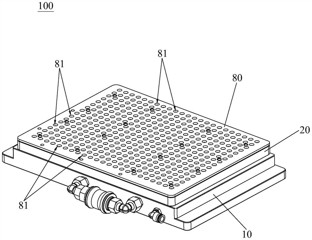
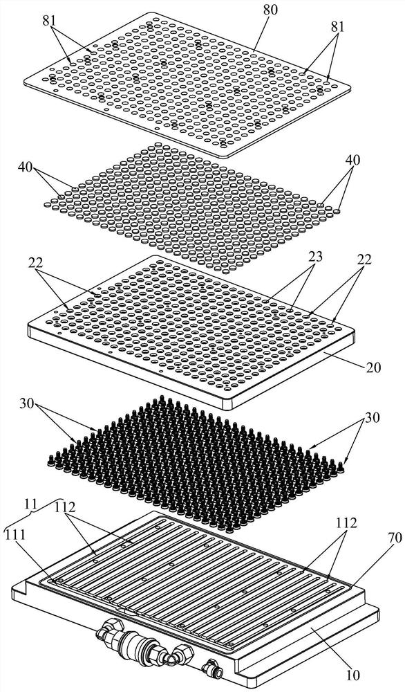
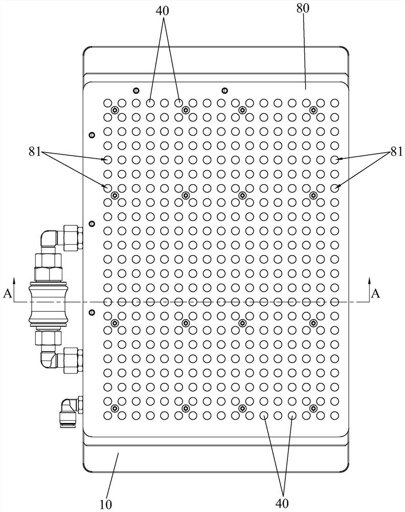
[0026] see Figure 1 to Figure 6 , the base 10 of the suction cup device 100 of the present application, the cover plate 20 and some air-tight components 30, the top of the base 10 is provided with a ventilation groove 11, the cover plate 20 is airtight and fixedly covered on the top of the ventilation groove 11, and the ventilation groove 11 A ventilation chamber (not marked in the figure) is formed between the bottom of the cover plate 20, the ventilation chamber is connected to an external vacuum pumping device, and the venting chamber is vacuumed by the external vacuum pumping device, and the external The specific structure of the vacuum pumping device is well known to those skilled in the art, so details will not be repeated here. The bottom of the cover plate 20 is vertically u...


PUM


Abstract

The invention provides a suction cup device which comprises a base, a cover plate and a plurality of air closing assemblies. A ventilation groove is formed in the top of the base, the cover plate fixedly covers the top of the ventilation groove in a closed mode, a ventilation cavity is formed between the ventilation groove and the bottom of the cover plate, and plurality of mounting grooves for mounting the air closing assemblies in a one-to-one correspondence manner are vertically and upwards formed in the bottom of the cover plate. The top of the cover plate is vertically and downwards provided with adsorption grooves right facing the upper portions of the mounting grooves in a one-to-one mode, and isolation layers are vertically provided with first ventilation holes and second ventilation holes. Each air closing assembly comprises a ventilation nozzle, a sealing valve body and an elastic piece, wherein the ventilation nozzle is fixedly installed in the corresponding mounting groove in a sealed mode, the sealing valve body is vertically and movably arranged at the top of the ventilation nozzle, the sealing valve body is located under the corresponding first ventilation hole, and the sealing valve body is provided with a ventilation position and an air closing position in the vertical direction. Elastic pieces abut against the positions between the sealing valve bodies and the ventilation nozzles, and the elastic pieces constantly drive the sealing valve bodies to move towards the ventilation positions.

Description

technical field [0001] The present application relates to the technical field of fixing devices for machine tool processing, in particular to a suction cup device. Background technique [0002] As we all know, in the process of processing workpieces by machine tools, it is often necessary to use suction cups to fix the workpieces to be processed. [0003] When the traditional adsorption suction cup fixes the workpiece, the workpiece is placed on the suction cup first, and the part of the suction cup that is not covered by the workpiece is sealed with a rubber strip to prevent the part of the suction cup that is not covered by the workpiece from being in the suction gas all the time. The state can also ensure that the suction cup has sufficient adsorption and fixing force on the workpiece. Therefore, when replacing or moving the workpiece, it is necessary to reciprocate the assembly and disassembly of the rubber strip many times, and the operation is very cumbersome and comp...

Claims


Application Information

Patent Timeline
Patent Type & Authority Applications(China)
IPC IPC(8): B23Q3/08B23Q3/18
CPCB23Q3/088B23Q3/18
Inventor 张小军刘长文谭晓军
Owner 张小军
Why Eureka
Try Eureka