
Method for adjusting position of support joint

A node position and support technology, applied in bridge parts, special data processing applications, bridges, etc., to solve the problem of offset and achieve the effect of full life management

Active Publication Date: 2021-12-21
SHANGHAI RB RUBBER ISOLATOR TECH
View PDF18 Cites 0 Cited by
  • Summary
  • Abstract
  • Description
  • Claims
  • Application Information

AI Technical Summary

Problems solved by technology

[0003] The purpose of the present invention is to provide a method for adjusting the position of the support node, which is used to solve the multi-directional displacement adjustment problem of the existing support during service

Method used


Image

  • Method for adjusting position of support joint
  • Method for adjusting position of support joint
  • Method for adjusting position of support joint

Examples


Embodiment Construction

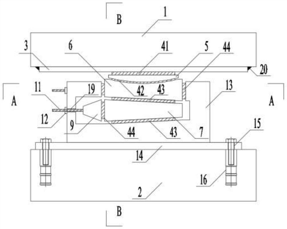
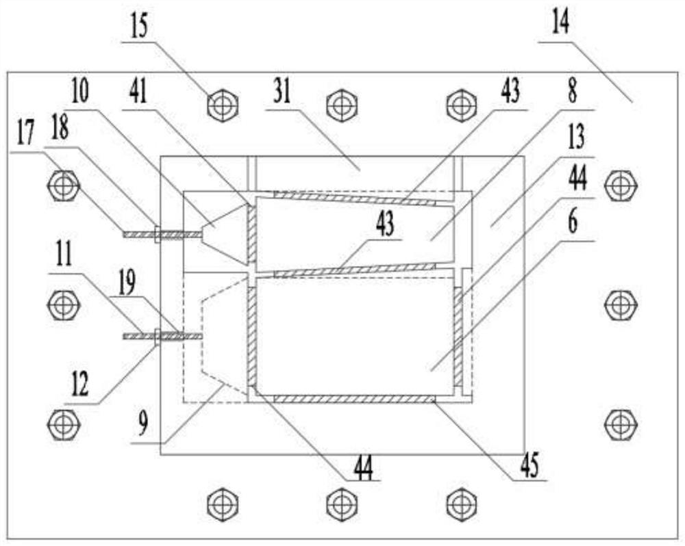
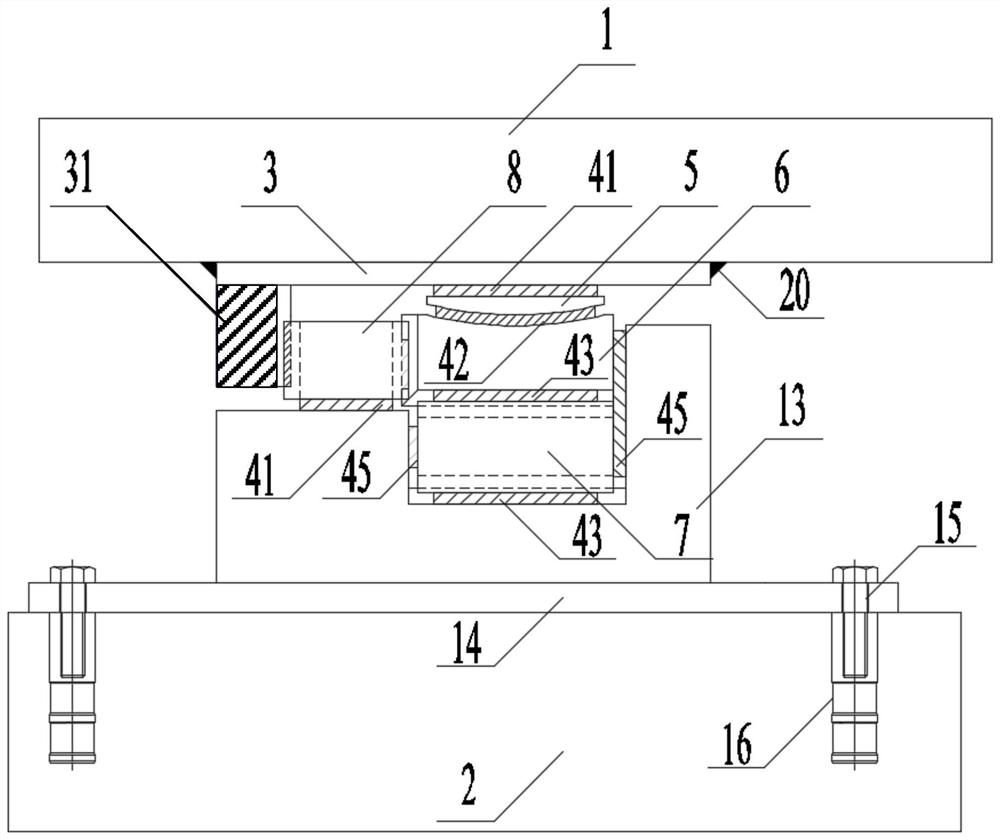
[0042] A method for adjusting the position of the support node in the present invention will be described in further detail below in conjunction with the accompanying drawings. It should be understood that the following examples are only used to illustrate the present invention but not to limit the scope of the present invention. In the description of the embodiments of the present invention, orientation descriptions are involved, for example, orientations or positional relationships indicated by horizontal, vertical, oblique, inner, outer, left, right, front, rear, etc. are based on the orientations or positional relationships shown in the drawings. The positional relationship is only for the convenience of describing the present invention and simplifying the description, but does not indicate or imply that the referred device or element must have a specific orientation, be constructed and operated in a specific orientation, and thus should not be construed as limiting the pre...


PUM


Abstract

The invention discloses a method for adjusting the position of a support joint. The method comprises the steps of determining the mapping relation between the translation displacement of an adjusting screw rod and the displacement change of a support by determining the pressure load, the shear load and the inclination of a wedge-shaped block borne by the support; according to the displacement mapping relation, designing measuring rulers used for displacement adjustment, and the distance between the measuring rulers representing the vertical displacement change or the horizontal displacement change of the support. The position of the displacement adjusting wedge-shaped block on the inner wall of the lower support can be adjusted by rotating the adjusting screw rod, the vertical height and the horizontal position of the upper support plate of the support are adjusted, the position of the adjusting screw rod is fixed through a displacement locking nut, the safety of the structure is improved, and the support has the advantages of being low in manufacturing cost, excellent in weather resistance, simple in structure, safe, reliable and the like.

Description

technical field [0001] The invention relates to the technical field of civil engineering bearings, in particular to a method for adjusting the positions of bearing nodes. Background technique [0002] In civil engineering structures, especially in building structures and bridge structures, steel bearings are used for the fixed connection of upper and lower members of the structure. As the key component of the boundary of the engineering structure, the support may be displaced vertically or horizontally due to factors such as structural deformation, foundation settlement or dynamic load during service, and the flatness of the support installation directly affects the safety and comfort of the structure . Therefore, it is of great significance to propose a safe, convenient and efficient method for adjusting the position of support nodes for structures with high flatness requirements, such as maglev viaducts. Contents of the invention [0003] The purpose of the present inv...

Claims


Application Information

Patent Timeline
IPC IPC(8): E01D19/04E04B1/36G06F30/13
CPCE01D19/042E01D19/048E04B1/36G06F30/13
Inventor 欧阳郁汀施竹珺
Owner SHANGHAI RB RUBBER ISOLATOR TECH
Learn More