A key + password mixed structure anti-theft lock cylinder

A technology of mixed structure and anti-theft lock cylinder, which is applied in combination locks, locks with turning keys, keys, etc., can solve the problems of mechanical anti-theft locks, such as untrue names, reduced lock security, and high labor intensity, so as to improve productivity, Improve productivity and save copper consumption

Active Publication Date: 2019-09-03
刘生豹
View PDF6 Cites 0 Cited by
  • Summary
  • Abstract
  • Description
  • Claims
  • Application Information

AI Technical Summary

Problems solved by technology

Of these three types of structural locks, the flat key lock was first invented, and the design pins were three to five. Later, in order to prevent theft and improve the security of the lock, a cross key lock and a sleeve key lock were invented. There are seven gears, and the sleeve key lock pins are designed to be seven gears. The number of pins is increased, which improves the security. However, the number of lock cylinder pins is too many, which will bring many quality problems to the manufacturing. The most annoying thing in the lock industry is the pins. Hole drilling process, because the hole is drilled on the outer circle of the lock cylinder, at present, the hole is still drilled manually on a drilling machine, which is labor-intensive. The problem of the coaxiality of the upper and lower marble holes has not been effectively solved. Quality problems are dealt with by enlarging the chamfer and hole diameter. The result is that the hole diameter is too large. Confidentiality
"Currently the theft is serious, the mechanical anti-theft lock has become famous but not true, the current situation is very grim

Method used


Image

  • A key + password mixed structure anti-theft lock cylinder
  • A key + password mixed structure anti-theft lock cylinder
  • A key + password mixed structure anti-theft lock cylinder

Examples


Embodiment Construction

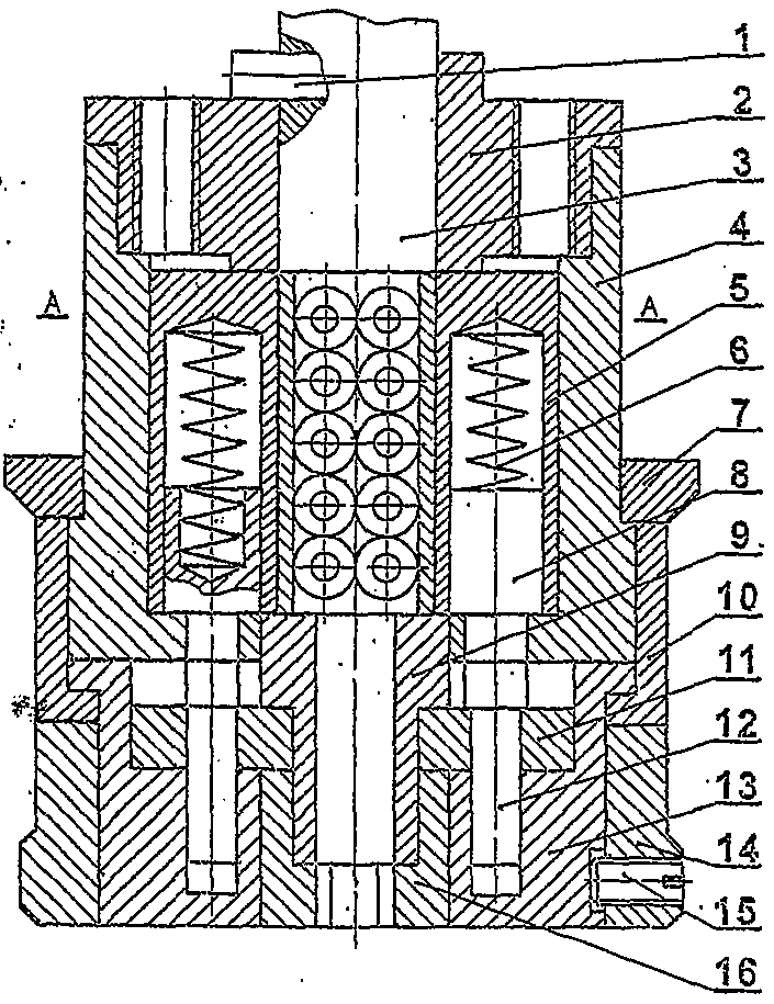
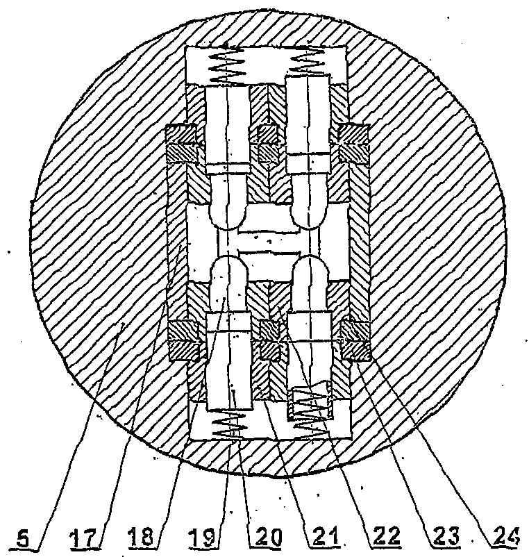
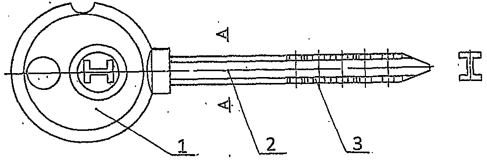
[0013] The present invention will be further described below in conjunction with accompanying drawing:

[0014] figure 1 It is the lock cylinder assembly drawing of the present invention, figure 2 yes figure 1 The cross-sectional view of A-A, an anti-theft lock cylinder with a key ten password mixed structure of the present invention, is composed of a 20-gear pin mechanism, a password mechanism and an I-shaped key. The 20-gear pin mechanism includes a positioning shaft 1, a lock cylinder cover 2, and a splint Upper fixed shaft 3, lock core seat 4, splint disk 5, compression spring 6, washer 7, lower splint fixed shaft 9, keyhole sleeve 16, splint backing plate 17, lower marble 18, pin compression spring 19, upper marble 20, Upper pinch tube 21, lower pinch tube 22, upper splint 23, lower splint 24, the pin design 20 gears of this pin mechanism are 4 rows of 5 gears, and design 4 gears of closing pins among the 20 pins, the so-called sealing pins are the Under normal condit...


PUM


Abstract

The invention discloses an anti-theft lock core of a key and code mixed structure. The lock core is composed of a 20-gear marble mechanism, a code mechanism and an H-shaped key. A marble of the anti-theft lock core is designed into 20 gears divided into four rows, each row contains 5 gears, the gear number is the highest record of that of global tumbler locks, and the four-gear sealed marble and the code mechanism are additionally arranged, so that the possibility that the lock core is technically unlocked is completely eliminated. Upper and lower clamping plates of the anti-theft lock core are thin plates which are made of copper materials and can be automatically produced on a high-speed punch with materials (DOBBY punch: the speed is 300 to 1000 times / minute), and stamping is performed by using a die, so that the productivity is increased, and the problem of different axis degrees of marble holes in the upper and lower clamping plates is solved. Shaft parts of the anti-theft lock core are processed on an automatic lathe, so that the full-automatic processing of the parts is realized, the productivity of the lock core is increased by 10 times, the consumption of the copper materials is reduced by 60%, the cost is greatly reduced, and the anti-theft lock core has a high performance-to-price ratio which is the greatest advantage based on the market.

Description

technical field [0001] The invention relates to a mechanical structure lock, in particular to an anti-theft lock core with a key+password mixed structure. Background technique [0002] The tumbler structure lock has been invented for more than 100 years. Because of its reliable structure and convenient opening, it has been adopted by various locks. At present, the tumbler structure locks on the market can be divided into three types according to the arrangement of the pins: one uses a flat key, and the pins are in the The outer circle of the lock cylinder is arranged in a straight line. One uses a cross key, and the marbles are arranged around the outer circle of the lock cylinder. Another kind adopts the sleeve key, and the marbles are arranged around the end face of the lock cylinder. Of these three types of structural locks, the flat key lock was first invented, and the design pins were three to five. Later, in order to prevent theft and improve the security of the lock...

Claims


Application Information

Patent Timeline
Patent Type & Authority Patents(China)
IPC IPC(8): E05B27/02E05B37/20E05B19/06
Inventor 刘生豹
Owner 刘生豹
Why Eureka
Try Eureka