Rod bending, inserting and sleeving machine

A technology of bar and bending insertion, which is applied in metal processing, metal processing equipment, manufacturing tools, etc., can solve the problems of low assembly efficiency and increased manpower input, and achieve the effects of firm fixation, reduced labor intensity, and improved work efficiency

Inactive Publication Date: 2018-09-07
DONGGUAN UNIV OF TECH
View PDF0 Cites 0 Cited by
  • Summary
  • Abstract
  • Description
  • Claims
  • Application Information

AI Technical Summary

Problems solved by technology

[0003] When reinforcing some arc-shaped steel frames, such as Figure 7 , it is necessary to align the bar 22 with the steel frame socket 150 of the curved steel frame 15, and extend into the steel frame socket 150, but when inserting, because it is a curved steel frame 15, the straight bar 22 cannot be inserted directly, now Some assembly methods are carried out by man-machine cooperation. The bar 22 is bent by a bending machine in advance, and then the bar 22 is inserted into the arc-shaped steel frame 15 through manual handling, hole alignment, and machine push. ; In this way, on the one hand, the input of manpower is increased, and on the other hand, there is a problem of low assembly efficiency

Method used


Image

  • Rod bending, inserting and sleeving machine
  • Rod bending, inserting and sleeving machine
  • Rod bending, inserting and sleeving machine

Examples


Embodiment Construction

[0030] In order to enable those skilled in the art to better understand the technical solution of the present invention, the present invention will be described in detail below in conjunction with the accompanying drawings. The description in this part is only exemplary and explanatory, and should not have any limiting effect on the protection scope of the present invention. .

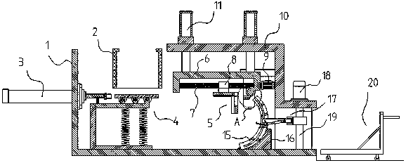
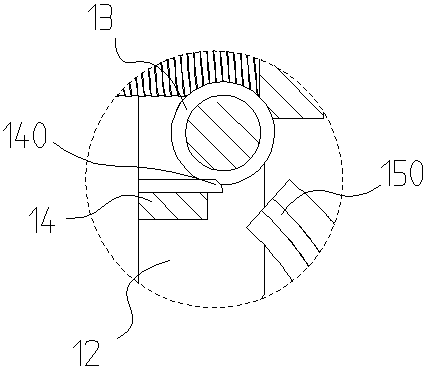
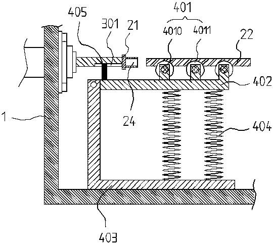
[0031] Such as Figure 1-Figure 9 Shown, the concrete structure of the present invention is: comprise frame 1; It also comprises automatic unloading mechanism 2, material pallet mechanism 4 and material propulsion mechanism 5, the upper end of described material pallet mechanism 4 and automatic blanking mechanism 2 The outlet of the material is connected with each other, and the lower end is erected vertically on the frame 1; the side end of the frame 1 is provided with a hydraulic push cylinder 3 that pushes the material to the material propulsion mechanism 5, and the end of the piston rod of the hydr...


PUM


Abstract

The invention discloses a rod bending, inserting and sleeving machine which comprises a rack, an automatic discharging mechanism, a material supporting plate mechanism, a material propulsion mechanismand a hydraulic pushing cylinder. The tail end of a piston rod of the hydraulic pushing cylinder is connected with an inserting push plate. An upper bottom plate and a lower bottom plate are arrangedon the rack. Jacking air cylinders are fixed to the upper bottom plate. Push rods of the jacking air cylinders are connected with a connecting frame. A screw is arranged on the connecting frame. Thematerial propulsion mechanism is in threaded connection with the screw through a sliding seat. An upper press roller and a lower press plate are arranged on the lower bottom plate, the upper press roller and a drive motor are connected through a core shaft, annular grooves are formed in the upper press roller, and a bending channel is formed by the annular grooves and an arc passing segment on thelower press plate. According to the aim, the rod bending, inserting and sleeving machine is provided for solving the problems, automatic assembling is adopted, whole assembling is in the faster and more convenient process, the labor intensity of workers is reduced, and the work efficiency is improved.

Description

technical field [0001] The invention belongs to the field of assembly, and in particular relates to a bar material insertion arc-shaped steel frame, in particular to a bar material bending and inserting machine. Background technique [0002] In the process of structural design, there may be situations where the overhanging surface of the structure is too large, or the span is too large. Add a reinforcement plate, commonly known as a reinforcement rib (JIN rib in engineering), to increase the strength of the joint surface. The characteristic is that it needs to be repaired for the steel structure of the factory building, bridge construction, large openings or the side of the staggered part, and the bridge over the street. reinforcement. [0003] When reinforcing some arc-shaped steel frames, such as Figure 7 , it is necessary to align the bar 22 with the steel frame socket 150 of the curved steel frame 15, and extend into the steel frame socket 150, but when inserting, beca...

Claims


Application Information

Patent Timeline
Patent Type & Authority Applications(China)
IPC IPC(8): B23P19/00B21D7/00
CPCB23P19/00B21D7/00
Inventor 白云李川曾波
Owner DONGGUAN UNIV OF TECH
Why Eureka
Try Eureka