Anti-backflow flushing drainage device

An anti-reflux and drainage tube technology, applied in suction devices, valves, other medical devices, etc., can solve the problems of blood clots and sundries that cannot be eliminated, infection, and endanger the life of patients, and achieve the elimination of blood clots or sundries. risk of obstruction of the device, the effect of operating comfort

Pending Publication Date: 2021-12-24
山东颐诺医疗科技有限公司
View PDF0 Cites 0 Cited by
  • Summary
  • Abstract
  • Description
  • Claims
  • Application Information

AI Technical Summary

Problems solved by technology

[0002] In laparoscopic surgery, it is usually necessary to use a flushing and drainage device to flush and drain the patient's surgical site to remove peritoneal effusion, blood clots and debris, which is convenient for surgical visualization and postoperative recovery. However, the existing flushing and drainage devices are often Fluid reflux leads to infection, the incidence rate is high, and severe cases endanger the lives of patients
Most of the solutions are devices that only allow one-way flow, such as one-way valves and reverse osmosis membranes, in flushing and drainage devices. Fluid can not be discharged, which is not conducive to postoperative recovery. Therefore, it is necessary to improve the existing irrigation and drainage catheter device to improve the drainage effect and reduce the infection caused by effusion reflux.

Method used


Image

  • Anti-backflow flushing drainage device
  • Anti-backflow flushing drainage device
  • Anti-backflow flushing drainage device

Examples


Embodiment Construction

[0034] The above-mentioned content of the present invention will be further described in detail through specific implementation in the form of examples below, but it should not be understood that the scope of the above-mentioned theme of the present invention is limited to the following examples. All technologies realized based on the above contents of the present invention belong to the scope of the present invention. Unless otherwise specified, the following examples were completed using conventional technical operations.

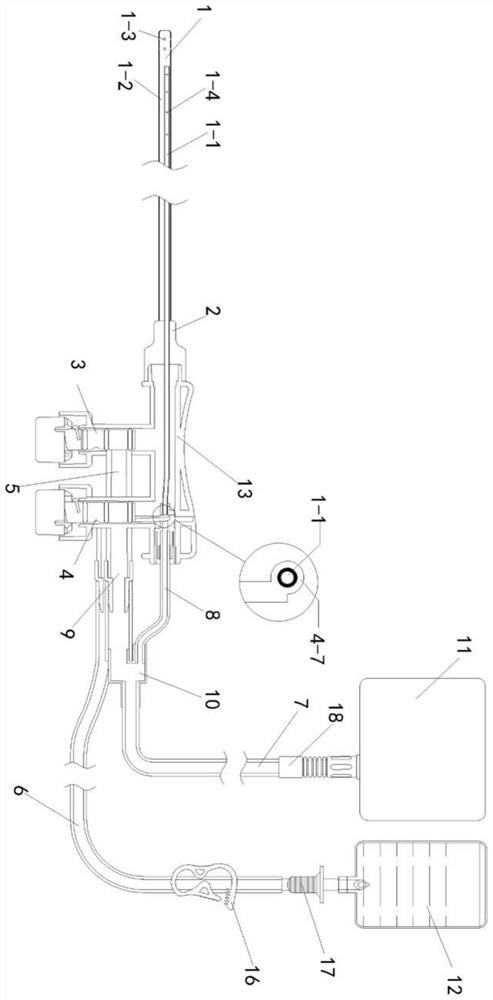
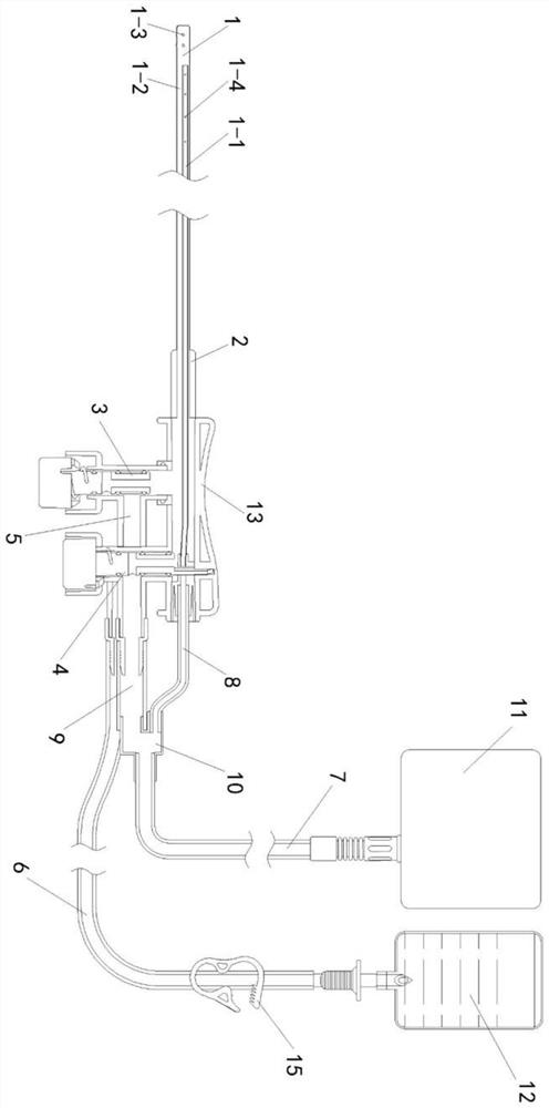
[0035] Such as figure 1 As shown, an anti-reflux flushing and drainage device includes a flushing and drainage tube 1, a flushing control valve 3, a drainage control valve 4, a flushing channel 5, a drainage channel 9, a flushing liquid source 12, and a negative pressure source 11, wherein:

[0036] The irrigation and drainage tube 1 is composed of an inner tube 1-1 nested in an outer tube 1-2, the front end of the outer tube 1-2 is provided with a side ...


PUM


Abstract

The invention relates to the field of medical instruments, in particular to an anti-backflow flushing drainage device. The anti-backflow flushing drainage device comprises a flushing drainage pipe, a flushing control valve, a drainage control valve, a flushing channel, a drainage channel, a flushing fluid source and a negative pressure source, wherein the flushing drainage pipe is formed by nesting an inner pipe in an outer pipe, a side hole is formed in the front end of the outer pipe, and a drainage hole is formed in the inner pipe; the rear end of the outer pipe and a connecting pipe are fixed outside the inner pipe to form a cavity; and the flushing control valve and the drainage control valve are arranged at the position of the connecting pipe. A drainage valve rod is long enough and can support a valve block to ascend into a groove; and the distance from the upper end of a drainage through hole to the lower end of the drainage channel is larger than that from the boundary of the valve block to the inner diameter of the inner pipe. In this way, when the drainage through hole is used and descends to be blocked, the valve block still does not completely block the inner pipe and an inner pipe connecting pipe, and the time delay effect is achieved. Residual fluid flows back to a pipeline is drained to the maximum extent, and the flushing drainage pipe is divided into the inner pipe and the outer pipe which are respectively provided with the drainage hole and the side hole, so that the risk that the device is blocked by blood clots or sundries when waste fluid is sucked is eliminated, and safe and continuous drainage is ensured. Due to the arrangement of a grabbing plate, operation is more comfortable.

Description

technical field [0001] The invention relates to the field of medical devices, in particular to an anti-reflux flushing and drainage device. Background technique [0002] In laparoscopic surgery, it is usually necessary to use a flushing and drainage device to flush and drain the surgical site of the patient to remove peritoneal effusion, blood clots and debris, which is convenient for surgical visualization and postoperative recovery. However, the existing flushing and drainage devices are often Fluid reflux leads to infection, the incidence rate is relatively high, and severe cases endanger the lives of patients. Most of the solutions are devices that only allow one-way flow, such as one-way valves and reverse osmosis membranes, in flushing and drainage devices. Fluid can not be discharged, which is not conducive to postoperative recovery. Therefore, it is necessary to improve the existing irrigation and drainage catheter device to improve drainage effect and reduce infect...

Claims


Application Information

Patent Timeline
Patent Type & Authority Applications(China)
IPC IPC(8): A61M1/00A61M39/22
CPCA61M39/225
Inventor 范月波刘贵宝王丽丽吴波申家祥盖玉娟
Owner 山东颐诺医疗科技有限公司
Why Eureka
Try Eureka