Terminal floating filter of separate rainwater drainage system

A drainage system and filtration device technology, which is applied in the direction of runoff/rainwater treatment, filtration treatment, water/sewage treatment, etc., can solve problems such as troublesome maintenance, harsh hydraulic conditions, and influence on sedimentation effect, so as to ensure the safety of drainage , Easy cleaning and maintenance, and the effect of improving the interception rate

Inactive Publication Date: 2019-03-12
ZHEJIANG UNIV
View PDF0 Cites 0 Cited by
  • Summary
  • Abstract
  • Description
  • Claims
  • Application Information

AI Technical Summary

Problems solved by technology

Among them, during the cyclone sedimentation, due to the instability of the incoming water, the effect of the hydrocyclone is difficult to control stably, which will inevitably affect the sedimentation effect, and the removal rate of the total suspended solids is difficult to improve.
For the advection sedimentation tank, since the residence time is the main factor determining the sedimentation of suspended solids, the rainwater terminal treatment device of the advection sedimentation has a larger volume and requires a higher site area, which affects the promotion and application
However, the SS removal device based on the filtration principle has the problems of easy blockage of the filter layer, difficulty in cleaning the filter material, and troublesome maintenance in the later stage.
[0004] At present, the terminal purification devices of diversion system rainwater drainage systems for the removal of suspended solids in China mainly adopt the principle of advection sedimentation or swirl sedimentation tanks. These devices either occupy a large area, have high cost, or require relatively harsh hydraulic conditions. The head loss is relatively large, and there is still a big gap in the effect of rainwater pollution control

Method used


Image

  • Terminal floating filter of separate rainwater drainage system

Examples


Embodiment Construction

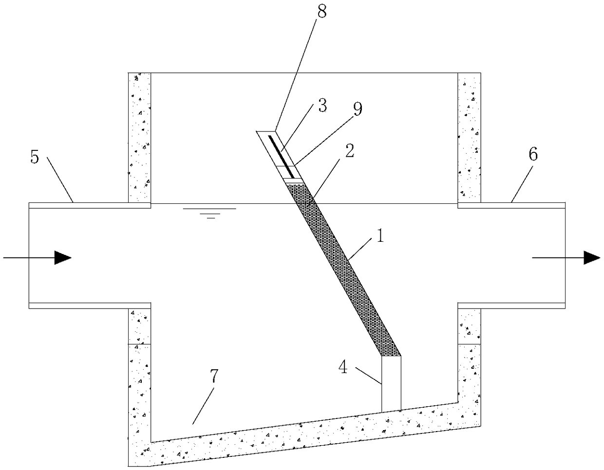
[0043] Such as figure 1 As shown, the floating filter device at the end of the divided rainwater drainage system in this embodiment includes a weir filter layer 8 composed of a stainless steel grid 1 , a suspended particle filter material 2 , and a telescopic pressure rod 3 , and a sedimentation zone 7 .

[0044] The stainless steel grid 1 is used as a container, including a front filter screen plate, a rear filter screen plate and two side plates.

[0045] The weir-type filter layer 8 is installed in the inspection well inclined to the side of the water inlet 5, and the water inlet 5 and the water outlet 6 are separated. The elevation of the weir top of the weir-type filter layer 8 can be adjusted. To ensure the outlet water quality of the device, it should be higher than the top elevation of the inlet pipe.

[0046] The weir-type filter layer 8 is installed on the buttress 4 at the bottom of the suspended shaft. Rainwater flows into the inspection well from the water inlet ...


PUM


Abstract

The invention discloses a terminal floating filter of a separate rainwater drainage system. The terminal floating filter comprises: a suspended matter filtering zone horizontally communicated with a water inlet and a water outlet; a mud settling zone arranged below the suspended matter filtering zone and used for collecting impurities filtered by the suspended matter filtering zone; an overflow zone arranged above the suspended matter filtering zone; a weir filtering layer that isolates the suspended matter filtering zone to filter rainwater and which includes a container with filter holes, asuspended particle filtering material fitted in the container and a fastener to compress the suspended particle filtering material in the container, wherein the side, facing the water inlet, of the container is tilted to the water inlet. The terminal floating filter is simple in structure and low in cost, has no need for power and is convenient to maintain; suspended matters in water and other pollutants attached to the suspended matters can be effectively removed; the weir floating filter layer helps well overcome the defects that mud film easily forms on the surface of a traditional filter,a filter layer blocks easily, and a filtering material is troublesome to wash; the filtering layer herein is convenient and thorough to wash.

Description

technical field [0001] The invention relates to the technical field of drainage filtration, in particular to a terminal floating filter device of a separate rainwater drainage system. Background technique [0002] Suspended solids are one of the important pollutants in stormwater runoff. Urban stormwater runoff contains a large amount of suspended solids, which mainly come from the debris produced by the corrosion of vehicles, exhaust gas produced by motor vehicles, atmospheric dry and wet sediments, tires and Substances produced by brake friction and smoke and dust released by residents' chimneys, etc. In addition to its own pollution, suspended matter is also the carrier of many other pollutants (such as heavy metals, N, P, oily substances, toxic oil hydrocarbons (PHC) and polycyclic aromatic hydrocarbons (PAHS), etc.). Suspended particles with large surface area. Before the rainwater runoff in the drainage pipe network is discharged into the receiving water body, the ef...

Claims


Application Information

Patent Timeline
Patent Type & Authority Applications(China)
IPC IPC(8): C02F9/02
CPCC02F1/001C02F1/52C02F2103/001C02F2201/002C02F2209/10C02F2303/14
Inventor 周永潮张土乔张仪萍方磊
Owner ZHEJIANG UNIV
Why Eureka
Try Eureka