Novel oxygenized air distributor for desulfurizing tower

A technology for oxidizing air and sparger, applied in chemical instruments and methods, gas treatment, gas dissolution, etc., can solve the problems of clogging the aperture of oxidizing air sparger, reducing the oxidation effect of desulfurization liquid, uneven distribution of oxidizing air, etc. The effect of blocking the oxidizing air distributor, overcoming easy corrosion, convenient and efficient use

Inactive Publication Date: 2017-09-29
LUOYANG GREEN ENVIRONMENTAL PROTECTION ENG CO LTD
View PDF0 Cites 0 Cited by
  • Summary
  • Abstract
  • Description
  • Claims
  • Application Information

AI Technical Summary

Problems solved by technology

[0005] In order to solve the above technical problems, the present invention provides a new type of oxidizing air distributor for desulfurization tower, which has a scientific and reasonable structural design, convenient and efficient use; it can solve the problem of uneven distribution of oxidizing air caused by air distributors with large apertures, reducing the The problem of the oxidation effect of the desulfurization liquid is solved, and at the same time, it also solves the problem of reducing the diameter of the aperture, increasing the number of holes, and easily causing the blockage of the aperture of the oxidation air distributor.

Method used


Image

  • Novel oxygenized air distributor for desulfurizing tower
  • Novel oxygenized air distributor for desulfurizing tower
  • Novel oxygenized air distributor for desulfurizing tower

Examples


Embodiment 1

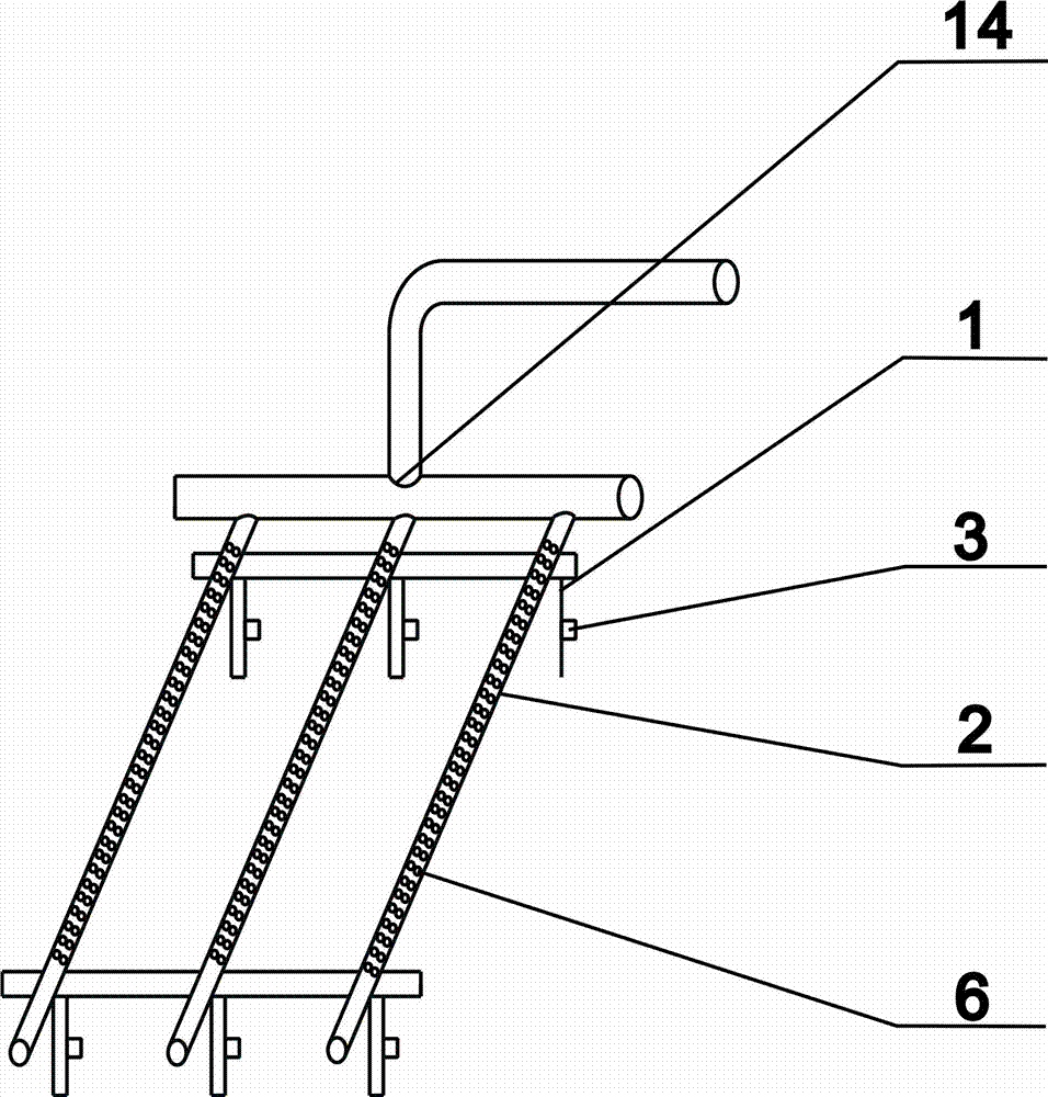
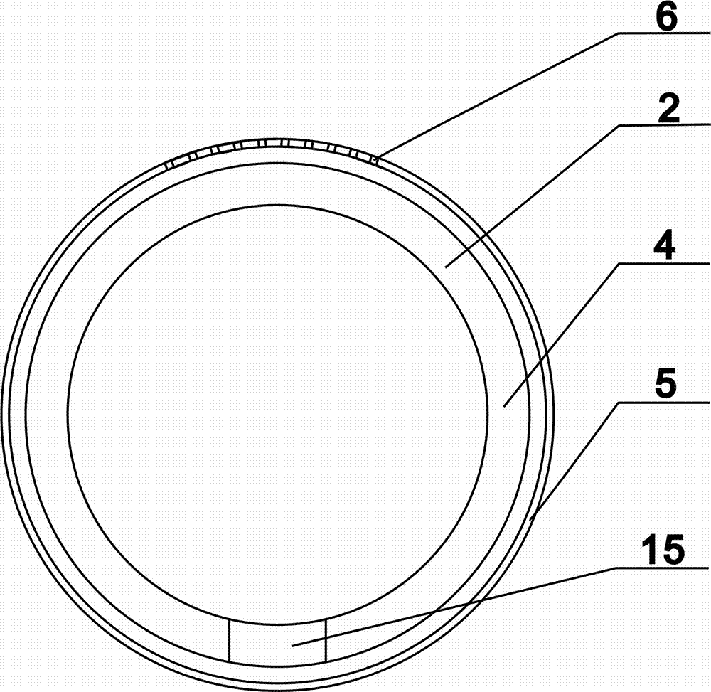
[0045] The aeration pipe 2 is composed of a skeleton pipe 4 and a distribution pipe 5. The inner diameter of the skeleton pipe is 80mm and the thickness is 8mm. The distribution pipe 5 is arranged on the outside of the skeleton pipe 4, and the upper part of the distribution pipe 5 is evenly provided with aeration holes 6. The diameter of the aeration holes 6 is 2mm. The distance between the aeration holes 6 and the aeration holes 6 The distance between them is 5 mm; the gap between the skeleton tube 4 and the distribution tube 5 is 1 mm.

Embodiment 2

[0047] The aeration pipe 2 is composed of a skeleton pipe 4 and a distribution pipe 5. The inner diameter of the skeleton pipe is 100mm and the thickness is 9mm. The diameter of the aeration hole 6 is 3mm, and the distribution pipe 5 is arranged on the outside of the skeleton pipe 4. The aeration hole 6 is evenly arranged on the upper part of the distribution pipe 5. The diameter of the aeration hole 6 is 3mm. The distance between them is 10 mm; the gap between the skeleton tube 4 and the distribution tube 5 is 1.5 mm.

Embodiment 3

[0049] The aeration pipe 2 is composed of a skeleton pipe 4 and a distribution pipe 5. The inner diameter of the skeleton pipe is 120mm and the thickness is 10mm. The distribution pipe 5 is arranged on the outside of the skeleton pipe 4, and the upper part of the distribution pipe 5 is uniformly provided with aeration holes 6. The diameter of the aeration holes 6 is 4mm. The distance between the aeration holes 6 and the aeration holes 6 The distance between them is 15 mm; the gap between the skeleton tube 4 and the distribution tube 5 is 2 mm.


PUM

PropertyMeasurementUnit
diameteraaaaaaaaaa
thicknessaaaaaaaaaa
diameteraaaaaaaaaa

Abstract

The invention discloses a novel oxygenized air distributor for a desulfurizing tower. Aerator pipes are parallelly and uniformly arranged on a bracket, one ends of the aerator pipes are fixedly connected with an air inlet main pipe, and the other ends of the aerator pipes are closed. The aerator pipe comprises a frame pipe and a distributor pipe, the frame pipe is arranged inside the aerator pipe, a vent hole is formed at the lower part of the frame pipe, the distributor pipe is arranged outside the frame pipe, and aeration holes are uniformly arranged just over the distributor pipe; a regulating device is arranged on a support bar of the bracket, support regulating holes are uniformly formed in the support bar of the bracket, two regulating plates are symmetrically arranged, and regulating holes are uniformly formed in the regulating plates. The novel oxygenized air distributor for the desulfurizing tower, disclosed by the invention, greatly increases the gas-liquid contacting area between oxygenized air and desulfurizing liquid, improves the desulfurization efficiency of SO2 and effectively overcomes the defect of blockage of the novel oxygenized air distributor.

Description

technical field [0001] The invention belongs to the technical field of forced aeration and oxidation of desulfurization liquid in desulfurization towers, and in particular relates to a novel oxidizing air distributor for desulfurization towers. Background technique [0002] With the development of industry, the continuous improvement of national environmental protection policies, and the enhancement of people's awareness of environmental protection, atmospheric environmental governance has been elevated to a new level of national strategy. However, SO2 in coal-fired flue gas has become the main cause of air pollution. For example, the content of SO2 in the flue gas emitted by thermal power plants, large industrial boilers, and industrial kilns is relatively high. the key of. [0003] The desulfurization devices for reducing SO2 can be divided into ammonia method, lime (stone) gypsum method, etc. according to their technical characteristics; among them, the oxidation of desu...

Claims


Application Information

Patent Timeline
Patent Type & Authority Applications(China)
IPC IPC(8): B01D53/73B01F15/02B01F3/04B01D53/80B01D53/50
CPCB01D53/73B01D53/502B01D53/80B01D2258/0283B01F23/23113B01F23/2311B01F35/712B01F23/2376
Inventor 刘旭孟凡颖李新宇苏茂郭召军张钰锟郭海龙李孟丽张刚刘嘉豪徐安
Owner LUOYANG GREEN ENVIRONMENTAL PROTECTION ENG CO LTD
Why Eureka
Try Eureka