

Gas extraction hole drilling vertical pneumatic intelligent water discharger and use method thereof
A gas extraction and water discharger technology, which is applied in gas discharge, drainage, mining equipment, etc., can solve the problems of high labor intensity, low water discharge efficiency, easy blockage, etc., and achieve the effect of overcoming high labor intensity and easy blockage.
- Summary
- Abstract
- Description
- Claims
- Application Information
AI Technical Summary
Problems solved by technology
Method used
Image

Examples
Embodiment 1
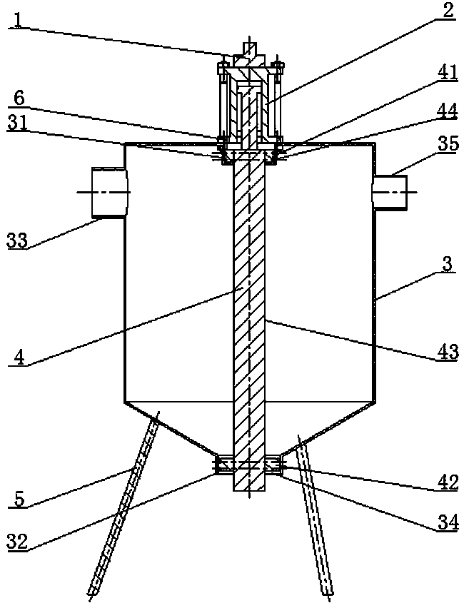
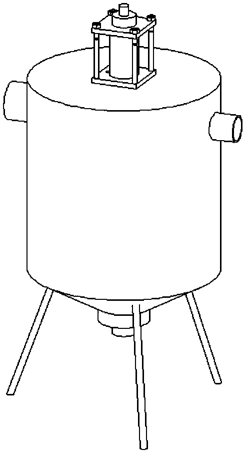
[0027] Embodiment one: if Figure 1 ~ Figure 3 As shown, the gas drainage drilling vertical pneumatic intelligent water release device of the present invention includes an air inlet pipe intelligent control valve 1, a cylinder 2, a water discharge device housing 3, a sealing transmission device 4, a bracket composition 5, and an air inlet pipe intelligent control valve. The valve 1 is connected with the cylinder 2, and is used to control the up and down movement of the piston of the cylinder 2; the sealing transmission device 4 is installed inside the drainer housing 3 and connected with the cylinder 2, and the up and down movement of the piston of the cylinder 2 drives the sealing transmission device 4 to move up and down; the bracket 5 is installed At the bottom of the drainer housing 3, it is used to support the drainer. Cylinder 2 is fixed on the outside of drainer housing 3, and the connecting portion between cylinder 2 and drainer housing 3 is provided with air vent 6, w...
Embodiment 2
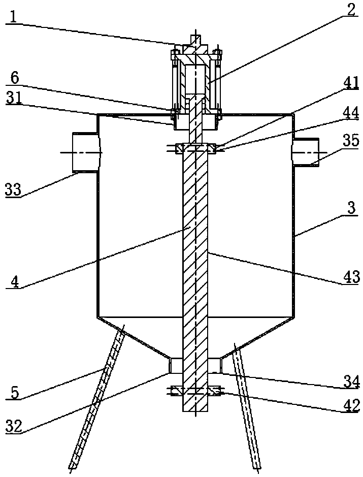
[0036] Embodiment two: if Figure 5 , Figure 6 , Figure 7 As shown, the difference from Embodiment 1 is that the taper angle at the bottom of the water dispenser housing 3 is reduced, and the water dispenser housing 3 is in a conical shape as a whole. Although the water storage capacity of the water dispenser is reduced, it is conducive to water discharge, especially for drainage. When the water discharged from the borehole contains more coal slime, it is more conducive to the discharge of the liquid-solid mixed medium.
Embodiment 3
[0037] Embodiment three: as Figure 8 , Figure 9 , Figure 10 As shown, the difference from Embodiment 1 is that the bottom structure of the drain housing 3 is changed, and the bottom is designed as a horizontal bottom. This structural design enables the drain to store more water, but the water discharged from the drainage borehole contains When there is a lot of coal slime, it is not conducive to slagging, and the water drainer is easy to accumulate slag and cause blockage. Therefore, when the water discharged from the extraction borehole contains less coal slime, this structure of water drainer can be selected.
PUM
 Abstract
Description
Claims
Application Information