Device for uniformly distributing gas

A technology of uniform distribution and gas, applied in the direction of electrical components, semiconductor/solid-state device manufacturing, discharge tubes, etc., can solve the problems of difficulty in ensuring repeatability, increasing the structure of the gas supply system, compact and complex machines, etc.

Pending Publication Date: 2021-12-24
PIOTECH CO LTD
View PDF0 Cites 0 Cited by
  • Summary
  • Abstract
  • Description
  • Claims
  • Application Information

AI Technical Summary

Problems solved by technology

In some cases, the non-reactive gas and the reactive gas are combined and advanced into the chamber. Due to the short travel distance, these gases are not fully mixed, resulting in differences in the thickness of the film on the surface of a single wafer, which affects the quality of the wafer. Yield
[0004] To solve the problem of uneven gas delivery, there are indepe

Method used


Image

  • Device for uniformly distributing gas
  • Device for uniformly distributing gas
  • Device for uniformly distributing gas

Examples


Embodiment Construction

[0019] In order to benefit the technical features, content and advantages of the present invention and the effects that can be achieved, the present invention is hereby combined with the accompanying drawings and described in detail as follows in the form of embodiments, and the purpose of the drawings used therein is only The purpose of illustration and auxiliary instructions is not limited to drawings and styles, and may not be the true proportion and precise configuration of the present invention after implementation, so the ratio and arrangement relationship of the attached drawings should not be interpreted and the present invention should not be limited to actual use The scope of rights in implementation shall be described first.

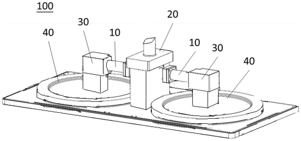
[0020] Please refer to figure 1 , is a schematic diagram showing that the device for uniformly distributing gas of the present invention is applied to semiconductor processing equipment. This figure only illustrates the upper cover of a doubl...


PUM


Abstract

The invention discloses a device for uniformly distributing gas, which is arranged between a plasma source generating device and a spraying assembly and comprises a body, the body is provided with a gas channel and a plurality of through holes, the gas channel is arranged at the central position of the body, the plurality of through holes are annularly arranged around the gas channel. The plurality of through holes are obliquely arranged in the body at an angle, each through hole is provided with an inlet and an outlet, and the aperture of the inlet is larger than that of the outlet.

Description

technical field [0001] The invention discloses a device for evenly distributing gas, especially a device for uniformly distributing gas applied to semiconductor process equipment. Background technique [0002] In the manufacture of highly integrated semiconductor devices, there is an increasing demand for the accuracy of various processes, such as thickness and uniformity control in thin film deposition processes. [0003] In the field of semiconductor manufacturing, the coating or etching of wafers is accomplished by using various gases to react on the surface of the wafer. Considering the issues of machine space and hardware cost, one or more reaction sources are often sent to each chamber during process reaction and chamber cleaning. Due to the difference in the flow resistance of each shunt, the total amount of reaction gas flowing to each chamber will be different, resulting in differences in the film thickness of the wafer surface between the chambers, and due to the ...

Claims


Application Information

Patent Timeline
IPC IPC(8): H01J37/32H01L21/67
CPCH01J37/3244H01J37/32449H01L21/67017
Inventor 周仁荒见淳一侯彬安超柴智
Owner PIOTECH CO LTD
Why Eureka
Try Eureka