
Discharging mechanism of centrifugal machine

A technology of unloading mechanism and centrifuge, applied in the field of centrifuges, can solve the problems of low unloading efficiency and trouble, and achieve the effect of improving the unloading rate

Inactive Publication Date: 2021-12-28
佛山市南海科粤机械有限公司
View PDF0 Cites 0 Cited by
  • Summary
  • Abstract
  • Description
  • Claims
  • Application Information

AI Technical Summary

Problems solved by technology

[0003] In order to solve the problem of unloading the centrifuge, the staff needs to manually scrape the material on the inner wall of the centrifuge drum for unloading. After scraping, it is necessary to use a brush to clean the material on the inner wall of the centrifuge drum. Troublesome problem, the object of the present invention is to provide a centrifuge discharge mechanism

Method used


Image

  • Discharging mechanism of centrifugal machine
  • Discharging mechanism of centrifugal machine
  • Discharging mechanism of centrifugal machine

Examples


Embodiment Construction

[0018] The implementation of the present invention will be illustrated by specific specific examples below, and those skilled in the art can easily understand other advantages and effects of the present invention from the contents disclosed in this specification.

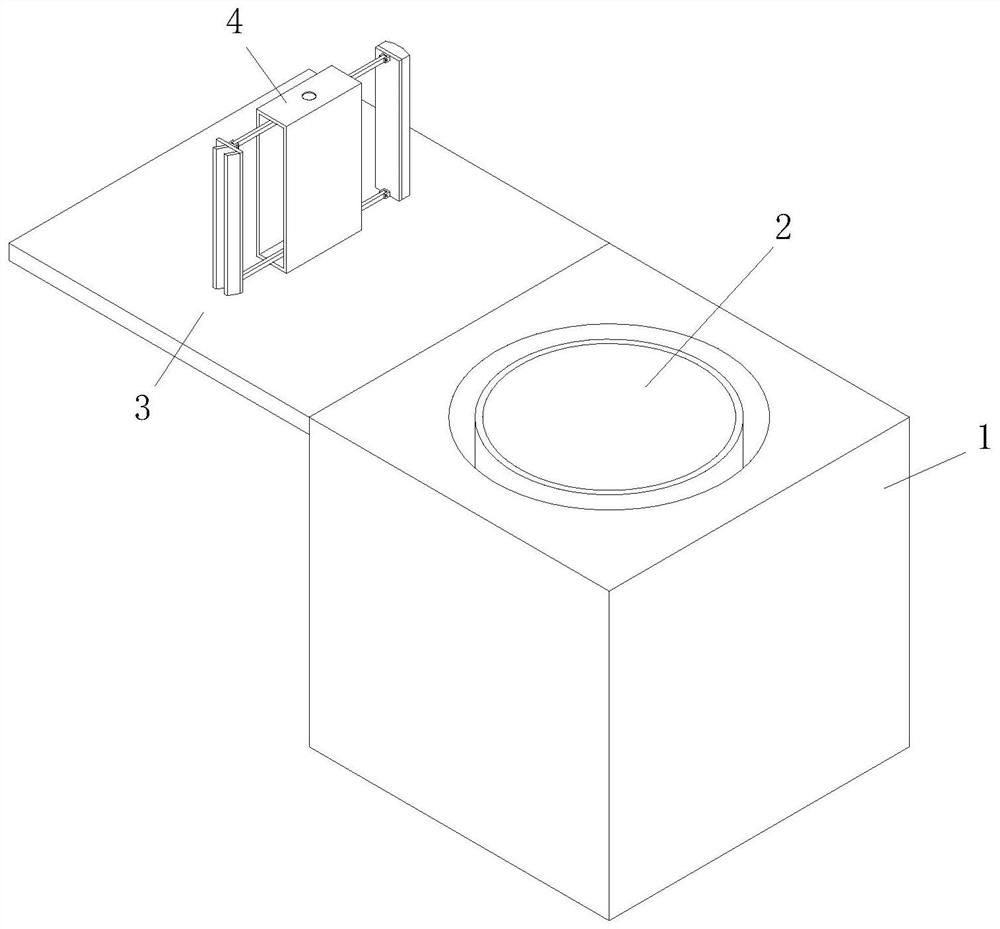
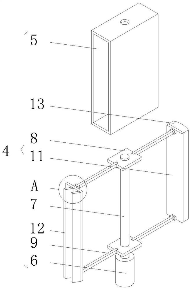
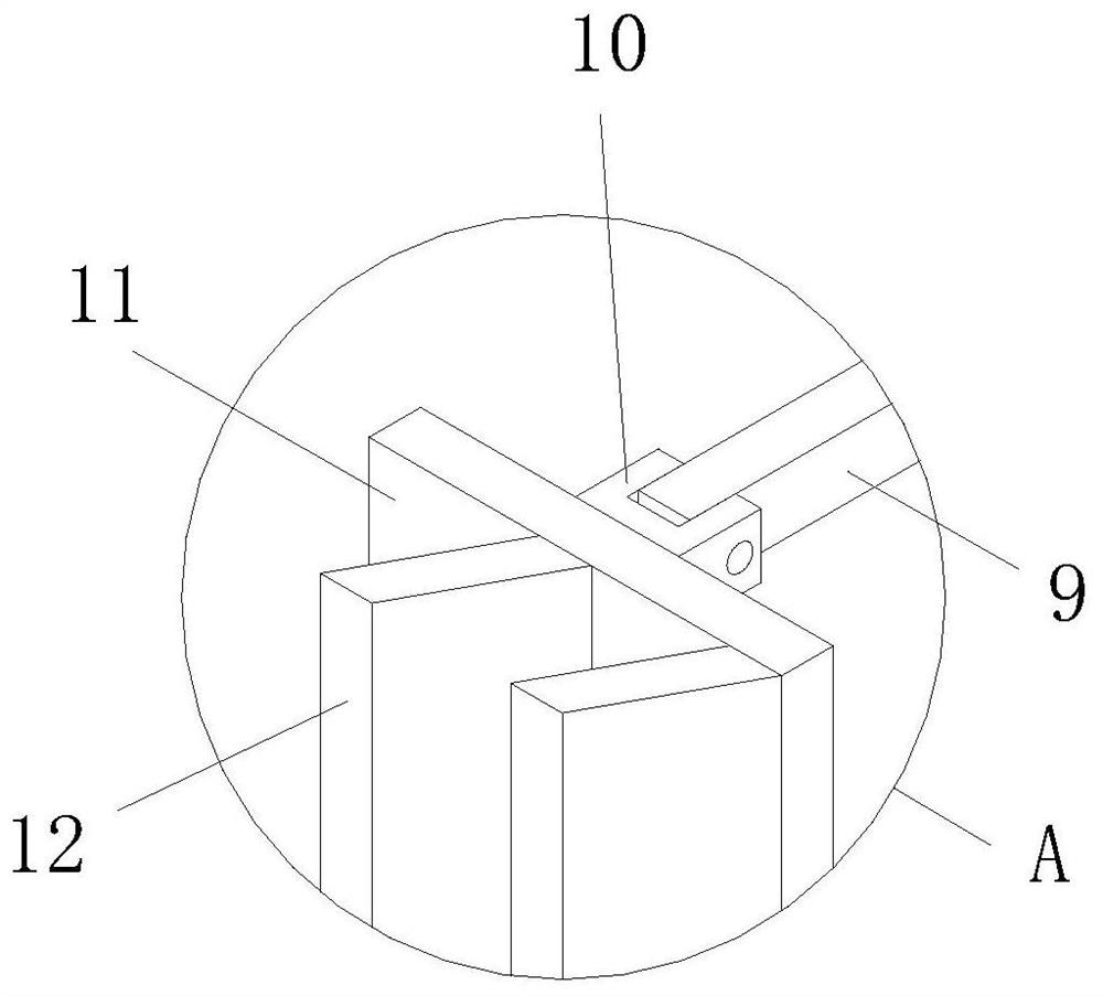
[0019] see Figure 1 to Figure 3 . It should be noted that the structures, proportions, sizes, etc. shown in the drawings attached to this specification are only used to match the content disclosed in the specification, for those who are familiar with this technology to understand and read, and are not used to limit the implementation of the present invention. Limiting conditions, so there is no technical substantive meaning, any modification of structure, change of proportional relationship or adjustment of size, without affecting the effect and purpose of the present invention, should still fall within the scope of the present invention. The disclosed technical content must be within the scope covered. At the sa...


PUM


Abstract

The invention discloses a discharging mechanism of a centrifugal machine, and relates to the technical field of centrifugal machines. The discharging mechanism of the centrifugal machine comprises a centrifugal machine body, a centrifugal roller is arranged on the inner wall of the centrifugal machine body, a centrifugal machine cover is hinged to the edge of the top of the centrifugal machine body, and a discharging mechanism body is installed on the centrifugal machine cover; the discharging mechanism body comprises a shell and a motor, the output end of the motor is in shaft connection with a lead screw, two movable plates are symmetrically connected to the outer portion of the lead screw in a threaded and penetrating mode, four supporting rods are symmetrically hinged to the two movable plates, four U-shaped blocks are hinged to the ends, away from the two movable plates, of the four supporting rods, two rectangular plates are fixedly connected to the side walls of the four U-shaped blocks, the side wall of one rectangular plate is fixedly connected with a scraping plate, and the side wall of the other rectangular plate is fixedly connected with a brush. The problems that during discharging of the centrifugal machine, a worker needs to manually scrape materials on the inner wall of a roller of the centrifugal machine for discharging, the materials on the inner wall of the roller of the centrifugal machine need to be brushed clean through the brush, the discharging efficiency is very low, and the discharging is very troublesome are solved.

Description

technical field [0001] The invention relates to the technical field of centrifuges, in particular to a centrifuge unloading mechanism. Background technique [0002] In the prior art, when the centrifuge is unloading, the staff needs to manually scrape the material on the inner wall of the centrifuge drum for unloading. After scraping, it is necessary to use a brush to clean the material on the inner wall of the centrifuge drum, and the unloading efficiency is very low. , and very troublesome, so we proposed a centrifuge unloading mechanism. Contents of the invention [0003] In order to solve the problem of unloading the centrifuge, the staff needs to manually scrape the material on the inner wall of the centrifuge drum for unloading. After scraping, it is necessary to use a brush to clean the material on the inner wall of the centrifuge drum. Troublesome problem, the object of the present invention is to provide a centrifuge discharge mechanism. [0004] In order to ach...

Claims


Application Information

Patent Timeline
Patent Type & Authority Applications(China)
IPC IPC(8): B04B11/08
CPCB04B11/08
Inventor 焦瑞明
Owner 佛山市南海科粤机械有限公司
Learn More