
Optical fiber sensing intelligent monitoring system

A technology of intelligent monitoring and optical fiber sensing, applied in the direction of rolling force/roll gap control, temperature control, etc., can solve the problems affecting the adjustment of the rolling mill, the large difference in the transverse box of the deformation resistance of the steel strip, etc., and achieve the effect of improving the monitoring accuracy

Pending Publication Date: 2021-12-28
欧开来
View PDF0 Cites 0 Cited by
  • Summary
  • Abstract
  • Description
  • Claims
  • Application Information

AI Technical Summary

Problems solved by technology

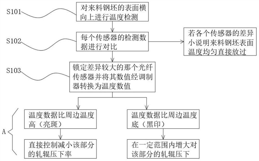
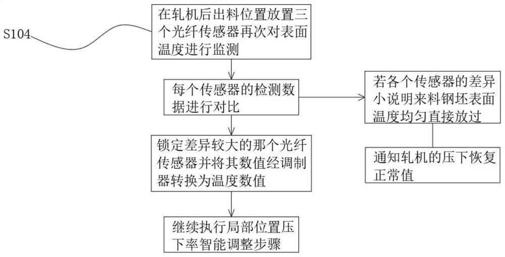
[0004] The present invention provides an optical fiber sensing intelligent monitoring system in order to overcome the problem in the prior art that the detection of the steel temperature is not accurate enough to cause the deformation resistance of the steel strip to be too large in the transverse direction, thereby affecting the adjustment of the rolling mill.

Method used


Image

  • Optical fiber sensing intelligent monitoring system
  • Optical fiber sensing intelligent monitoring system
  • Optical fiber sensing intelligent monitoring system

Examples


Embodiment Construction

[0027] The following will clearly and completely describe the technical solutions in the embodiments of the present invention with reference to the accompanying drawings in the embodiments of the present invention. Obviously, the described embodiments are only some, not all, embodiments of the present invention.

[0028] In describing the present invention, it should be understood that the terms "upper", "lower", "front", "rear", "left", "right", "top", "bottom", "inner", " The orientation or positional relationship indicated by "outside", etc. is based on the orientation or positional relationship shown in the drawings, and is only for the convenience of describing the present invention and simplifying the description, rather than indicating or implying that the referred device or element must have a specific orientation, so as to Specific orientation configurations and operations, therefore, are not to be construed as limitations on the invention.

[0029] In this example

...


PUM


Abstract

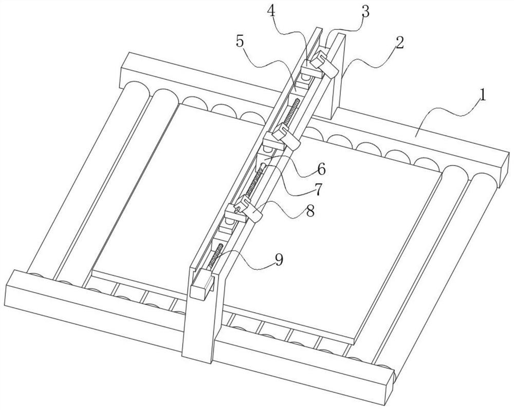
The invention belongs to the technical field of optical fiber sensing, particularly relates to an optical fiber sensing intelligent monitoring system. Aiming at the problem that the adjustment of a rolling mill is affected due to overlarge transverse box difference of deformation resistance of a steel belt caused by inaccurate detection of steel temperature in the prior art, the following scheme is provided. The system comprises monitoring devices erected on a front roller way and a rear roller way, the monitoring device comprises an arch-shaped supporting frame fixed between the upper surfaces of roller frames on the two sides of the roller way, the arch-shaped supporting frame comprises two vertical rods and a horizontal cross beam, a T-shaped sliding groove is formed in the upper surface of the horizontal cross beam, and a middle seat is fixed in the middle of the interior of the T-shaped sliding groove. When a steel billet passes through the monitoring device in use, the temperature of the steel billet can be monitored from the middle and the two sides correspondingly, the monitoring accuracy is improved, the two monitoring positions on the two sides can be adjusted along with the width change of the steel billet, and it is ensured that the monitoring positions on the two sides are located within the width range of the steel billet.

Description

technical field [0001] The invention relates to the technical field of optical fiber sensing, in particular to an intelligent monitoring system for optical fiber sensing. Background technique [0002] In the steel rolling production process, the steel billet is first sent to the heating furnace to be heated, and then rolled repeatedly in the preliminary rolling mill, and then rolled in the finishing mill. The temperature of the steel billet at each stage above has a great influence on the deformation resistance, The rolling pressure, the metallographic structure of the finished product, the grain size, the mechanical properties and the surface state of the strip all have a direct impact. The existing temperature control method in the steel rolling process is to use a thermometer to detect the steel tapping temperature of the heating furnace, the temperature before finishing rolling and the exit temperature of the finished product, etc., record the steel temperature of each s...

Claims


Application Information

Patent Timeline
IPC IPC(8): B21B37/74B21B37/58
CPCB21B37/74B21B37/58
Inventor 欧开来
Owner 欧开来
Learn More