
Injection molding mechanism and hot runner system

A runner, injection molding technology, applied in the field of hot runner mold, can solve problems such as increasing valve needle pressure, and achieve the effect of easy downward movement

Pending Publication Date: 2021-12-28
YUDO SUZHOU HOT RUNNER SYST
View PDF0 Cites 0 Cited by
  • Summary
  • Abstract
  • Description
  • Claims
  • Application Information

AI Technical Summary

Problems solved by technology

But in this way, when the valve needle moves down to reduce the flow rate or completely disconnect the flow path, the extruded plastic cannot be released, which increases the pressure of the valve needle's downward movement

Method used


Image

  • Injection molding mechanism and hot runner system
  • Injection molding mechanism and hot runner system
  • Injection molding mechanism and hot runner system

Examples


Embodiment Construction

[0023] The present invention will be described in detail below in conjunction with specific embodiments shown in the accompanying drawings. However, these embodiments do not limit the present invention, and any structural, method, or functional changes made by those skilled in the art according to these embodiments are included in the protection scope of the present invention.

[0024] In each drawing of the present application, some dimensions of structures or parts are exaggerated relative to other structures or parts for convenience of illustration, and therefore, are only used to illustrate the basic structure of the subject matter of the present application.

[0025] In addition, terms used herein such as "upper", "above", "under", "below", etc. to express relative positions in space are for convenience of description to describe a unit or feature as shown in the drawings relative to A relationship to another cell or feature. The terms of spatial relative position may be...


PUM


Abstract

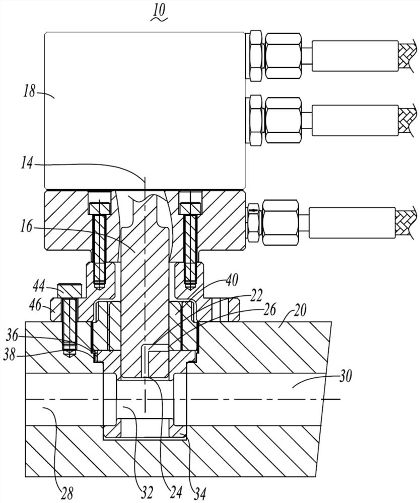
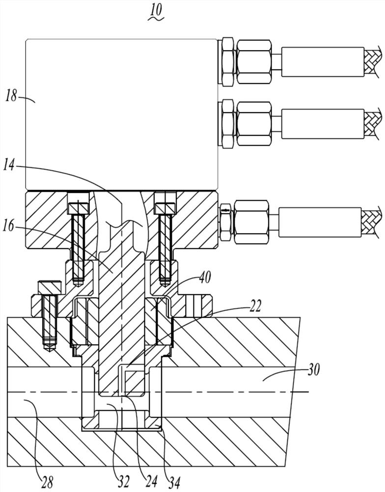
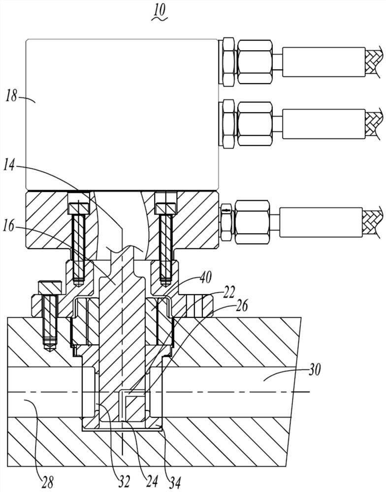
The invention discloses an injection molding mechanism and a hot runner system. The injection molding mechanism comprises a valve needle extending along the longitudinal axis, a driving device for driving the valve needle to reciprocate in the extending direction of the longitudinal axis, and a splitter plate. The splitter plate is provided with a glue inlet used for injecting plastic, a glue outlet used for flowing out the plastic and a runner communicating the glue inlet and the glue outlet. The valve needle is transversely intersected with part of the runner and is far away from the glue outlet, and when the valve needle moves along the longitudinal axis, the glue inlet sectional area of the runner can be adjusted. A pressure relief hole is formed in the valve needle, the valve needle is provided with a lower tail end and a side part, the pressure relief hole is provided with a first port and a second port which communicate with each other, the first port is positioned at the lower tail end of the valve needle, the second port is positioned at the side part, and the second port communicates with the runner. According to the injection molding mechanism and the hot runner system, the pressure relief hole is formed in the valve needle of the injection molding mechanism, and pressure relief can be effectively achieved through the pressure relief hole.

Description

technical field [0001] The invention relates to the field of hot runner molds, in particular to an injection molding mechanism and a hot runner system. Background technique [0002] At present, the injection molds commonly used in the injection molding industry are hot runner injection molds. Compared with ordinary molds, the plastic products injected through the hot runner system are of higher quality, and the hot runner system has the advantages of saving raw materials, improving production efficiency, and high degree of automation. [0003] The hot runner system includes a manifold, a hot nozzle assembly, and a valve needle that can be driven to reciprocate up and down by the drive cylinder. Injection port, the valve needle passes through the manifold flow channel and hot nozzle flow channel, and is driven to move up and down to open or close the injection port. The above structure makes the valve needle longer, and the valve needle will be deformed after long-term use. ...

Claims


Application Information

Patent Timeline
IPC IPC(8): B29C45/27B29C45/28
CPCB29C45/2703B29C45/2806
Inventor 李象烈
Owner YUDO SUZHOU HOT RUNNER SYST
Learn More