
Amphibious automobile power transmission system

A power transmission system and amphibious technology, which is applied to amphibious vehicles, motor vehicles, transportation and packaging, etc. It can solve the problems of difficulty in increasing the speed of vehicles on water, insufficient demand for water power, and heavy weight of power systems, so as to improve water navigation. The effect of speed, enhanced competitiveness, and large power demand

Active Publication Date: 2021-12-28
WUHU SHIPYARD CO LTD
View PDF4 Cites 0 Cited by
  • Summary
  • Abstract
  • Description
  • Claims
  • Application Information

AI Technical Summary

Problems solved by technology

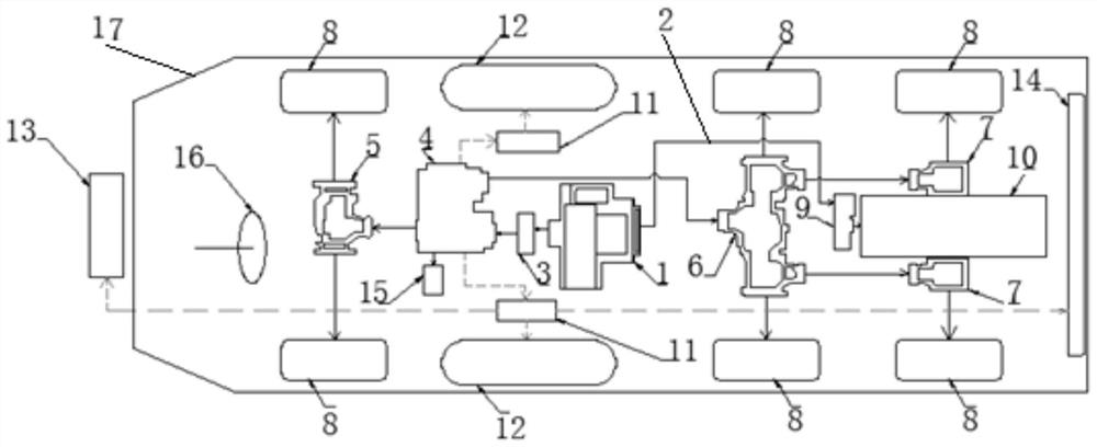
[0003] The technical problem to be solved by the present invention is: in the existing transmission mode of amphibious vehicles, the power system has a large weight, the overall transmission efficiency is not high, and the water power loss is large, the water power demand is insufficient, and the vehicle speed on water is difficult to increase. In view of the bottleneck on the water, a power transmission system for amphibious vehicles with a simplified structure is proposed. Through the unique water and land power transmission route, the length of the water transmission chain can be effectively reduced, and the engine power can be supplied to the water propeller to the greatest extent, so that it can obtain sufficient power to increase the speed of amphibious vehicles on water

Method used


Image

  • Amphibious automobile power transmission system

Examples


Embodiment Construction

[0020] Below with reference to the accompanying drawings, through the description of the embodiments, the specific embodiments of the present invention, such as the shape, structure, mutual position and connection relationship between the various parts, the role and working principle of the various parts, etc., will be further described. Detailed instructions:

[0021] as attached figure 1 As shown, the present invention is a power transmission system of an amphibious vehicle, and the power transmission system of the amphibious vehicle includes an engine 1, the engine 1 is arranged near the second shaft speed reduction bridge 6, and the engine 1 is located at the second shaft speed reduction bridge 6 In the front, the gearbox 3 is located in front of the engine 1, and the land transfer case 4 is located in front of the gearbox 3. The land transfer case 4 is connected to the first shaft deceleration bridge 5 and the second shaft deceleration bridge 6. The flywheel of the engine...


PUM


Abstract

The invention provides an amphibious automobile power transmission system applied to the technical field of amphibious automobiles. An engine (1) of the amphibious automobile power transmission system is arranged at a position close to a second shaft deceleration axle (6), the engine (1) is located in front of the second shaft deceleration axle (6), a gearbox (3) is located in front of the engine (1), a land transfer case (4) is located in front of the gearbox (3), the land transfer case (4) is connected with the first shaft deceleration axle (5) and the second shaft deceleration axle (6), and a flywheel of the engine (1) is connected with the water propeller (10) through the transmission shaft (2). According to the transmission system, through a unique water and land power transmission line, the length of a water transmission chain is effectively reduced; and the power of the engine is supplied to the water propeller to the maximum extent so that the water propeller obtains enough power, and the sailing speed of the amphibious automobile on water is increased.

Description

technical field [0001] The invention belongs to the technical field of amphibious vehicles, and more specifically relates to a power transmission system of an amphibious vehicle. Background technique [0002] The main transmission method and route of the traditional power of amphibious vehicles is basically to output the total power from the flywheel end of the engine to the transfer case. , Land drive, to obtain the power of propulsion on water and driving on land. The current conventional power transmission method, whether it is a water power transmission chain or a land power transmission chain, is long in terms of layout, resulting in a lot of loss in engine output power. Coupled with the efficiency factor of the transfer case itself, the efficiency of the transmission chain is further reduced. When the amphibious vehicle sails on the water, the power demand is much greater than the power of the vehicle when driving on land. In this traditional power transmission metho...

Claims


Application Information

Patent Timeline
Patent Type & Authority Applications(China)
IPC IPC(8): B60F3/00
CPCB60F3/003
Inventor 刘青峰赵永安刘观涛石正鹏王裕学夏诚浩方洁
Owner WUHU SHIPYARD CO LTD
Learn More