Textile thread traction device and traction method

A traction device and textile thread technology, which is applied in the directions of transportation and packaging, thin material handling, and filamentary material transportation, etc., can solve the problem that the guide frame and the textile thread are easy to wear out the textile thread, the constant universality of the traction wheel is not strong, and the There is no adjustment and other problems, to achieve the effect of improving toughness, wide applicability, and avoiding wear

Active Publication Date: 2021-12-28
ZHEJIANG TEXTILE & FASHION COLLEGE
View PDF6 Cites 1 Cited by
  • Summary
  • Abstract
  • Description
  • Claims
  • Application Information

AI Technical Summary

Problems solved by technology

[0002] Textile thread is closely related to people's production activities. Although most production-developed areas have adopted mechanized production to improve production efficiency, the rotary tube in the prior art can conveniently move and adjust the traction wheel flexibly, and the roll can be unwound through the unwinding wheel. For the textile thread, the traction wheel can facilitate the flexible movement and traction of the unwinding textile thread. However, due to the different thickness of the textile thread, the distance between the traction wheels is constant and the universality is not strong, and the textile thread needs to be guided when it is wound or used. , currently there is no structure to adjust the guiding direction, the friction between the guide frame and the textile thread is easy to wear the textile thread

Method used


Image

  • Textile thread traction device and traction method
  • Textile thread traction device and traction method
  • Textile thread traction device and traction method

Examples


Embodiment 1

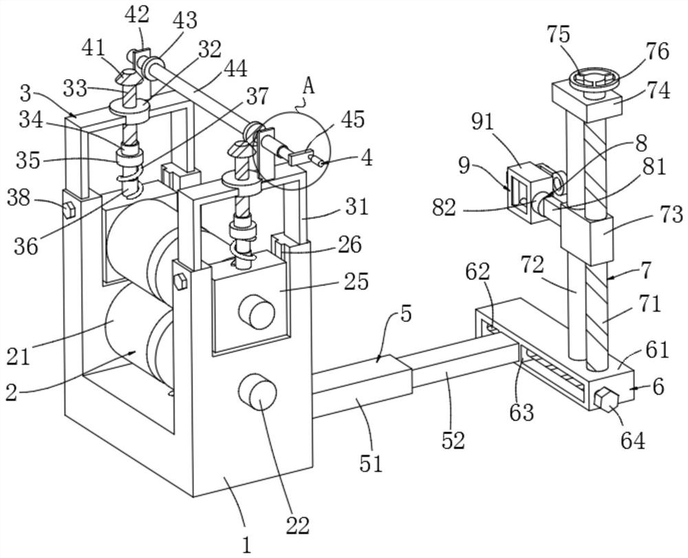
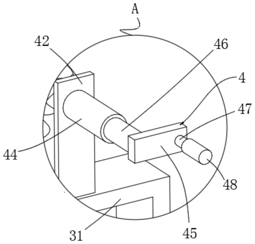
[0046] Example 1, please refer to Figure 1-10 , this embodiment provides a technical solution: a textile thread traction device, including a U-shaped frame 1, a traction power unit 2, a roller spacing adjustment unit 3, a roller spacing control unit 4, a distance adjustment unit 5, and a lateral adjustment unit 6. Height adjustment unit 7, corner adjustment unit 8 and rolling guide unit 9;

[0047] The two ends of the U-shaped frame 1 are respectively provided with slots, the traction power unit 2 is installed in the slot of the U-shaped frame 1, the roller spacing adjustment unit 3 is also installed on the U-shaped frame 1, and the roller spacing adjustment unit 3 is installed on the U-shaped frame 1. A roller spacing control unit 4 is installed, and one side of the U-shaped frame 1 is connected to a lateral adjustment unit 6 through a distance adjustment unit 5, and a height adjustment unit 7 is installed on the lateral adjustment unit 6, and the height adjustment unit 7 is...

Embodiment 2

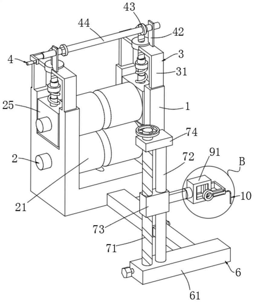
[0071] Example 2, please refer to Figure 4 , this embodiment provides a technical solution: a textile thread traction device, the structure of this embodiment is roughly the same as that of Embodiment 1, the difference is that it also includes a static electricity deriving unit 10, and the static electricity deriving unit 10 includes a side bending rod for installation 101, lead-out metal ring 102, metal conductive rod 103, conductive connection block 104 and grounding wire 105, the side of square frame 91 is connected with lead-out metal ring 102 by installing side bending rod 101, lead-out metal ring 102 is positioned at the front of square frame 91 , the lead-out metal ring 102 is connected to one end of the metal conductive rod 103 , and the other end of the metal conductive rod 103 is connected to one end of the ground wire 105 through the conductive connection block 104 . In order to prevent the textile thread from contacting the rolling shaft 95 with static electricity...


PUM


Abstract

The invention discloses a textile thread traction device and method. The textile thread traction device comprises a U-shaped frame, a traction power unit, a roll shaft distance adjusting unit, a roll shaft distance control unit, a distance adjusting unit, a transverse adjusting unit, a height adjusting unit, a corner adjusting unit and a rolling guide unit. Grooves are formed in the two ends of the U-shaped frame correspondingly, traction power units are installed in the grooves of the U-shaped frame, the roll shaft distance adjusting unit is further installed on the U-shaped frame, the roll shaft distance control unit is installed on the roll shaft distance adjusting unit, one side of the U-shaped frame is connected with the transverse adjusting unit through the distance adjusting unit, the height adjusting unit is mounted on the transverse adjusting unit, and the rolling guide unit is mounted on the height adjusting unit through the corner adjusting unit. The distance between roll shafts for traction can be adjusted according to the thickness of a textile thread, the application range is wide, the direction and angle of the textile thread can be guided, abrasion during guiding is avoided, and use is convenient.

Description

technical field [0001] The invention relates to the technical field of textile equipment, in particular to a textile thread traction device and a traction method. Background technique [0002] Textile thread is closely related to people's production activities. Although most production-developed areas have adopted mechanized production to improve production efficiency, the rotary tube in the prior art can conveniently move and adjust the traction wheel flexibly, and the roll can be unwound through the unwinding wheel. For the textile thread, the traction wheel can facilitate the flexible movement and traction of the unwinding textile thread. However, due to the different thickness of the textile thread, the distance between the traction wheels is constant and the universality is not strong, and the textile thread needs to be guided when it is wound or used. At present, there is no structure to adjust the guiding direction, and the friction between the guide frame and the tex...

Claims


Application Information

Patent Timeline
Patent Type & Authority Applications(China)
IPC IPC(8): B65H51/08B65H51/32B65H57/06B65H57/26
CPCB65H51/08B65H51/32B65H57/06B65H57/26
Inventor 袁利华朱远胜
Owner ZHEJIANG TEXTILE & FASHION COLLEGE
Why Eureka
Try Eureka