Double-acting clamping jig with shearing function

A dynamic clamping and jig technology, applied in the field of reclaiming jig, can solve the problems of material rod deformation and shorten the injection cycle, and achieve the effect of low cost, shortened injection cycle and compact structure

Pending Publication Date: 2021-12-31
NINGBO BEILONG PRECISION MOLDING
View PDF11 Cites 2 Cited by
  • Summary
  • Abstract
  • Description
  • Claims
  • Application Information

AI Technical Summary

Problems solved by technology

[0004] The present invention provides a double-action clamping fixture with a shearing function in order to overcome the disadvantages of clamping the injection molded product before it is completely cooled and shaped, and the possible interference with the punch of the punching machine caused by the deformation of the material rod in the prior art. , by shortening the material rod of the injection molded product, the possible interference with the punch of the stamping machine caused by the deformation of the material rod is avoided, so that the further shortening of the injection molding cycle becomes a reality

Method used


Image

  • Double-acting clamping jig with shearing function
  • Double-acting clamping jig with shearing function
  • Double-acting clamping jig with shearing function

Examples


Embodiment 1

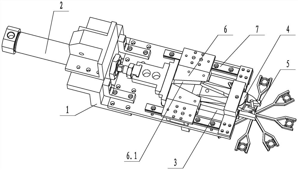
[0029] Such as figure 1 As shown, a double-action clamping fixture with shearing function includes a fixed frame 1, a first drive mechanism 2, a second drive mechanism 3, scissors 4, jaw blocks 5 and a first inclined push block 6, The first drive mechanism 2, the second drive mechanism 3 and the scissors 4 are respectively arranged on the fixed mount 1, the first drive mechanism 2 is a linear cylinder, the jaw block 5 is arranged below the scissors 4, and the first oblique pushing block 6 is connected to the fixed mount. 1 is slidably connected by the guide rail 7, the first driving mechanism 2 drives the first inclined push block 6 to slide, and the first inclined push block 6 is provided with a first guide groove 6.1, the first guide groove 6.1 is a V-shaped structure, and the first guide groove The big mouth of 6.1 faces the scissors 4, the handle of the scissors 4 is in contact with the side wall of the first guide groove 6.1, and the second driving mechanism 3 drives the ...

Embodiment 2

[0032]On the basis of Embodiment 1, the second drive mechanism 3 is a jaw cylinder. The structure can realize the independent driving of the jaw block 5, so that the jaw block 5 can clamp the material rod of the product under the action of the jaw cylinder.

Embodiment 3

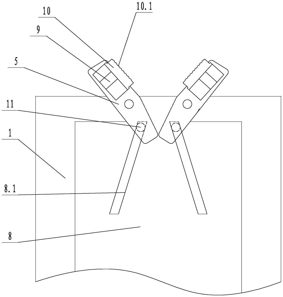
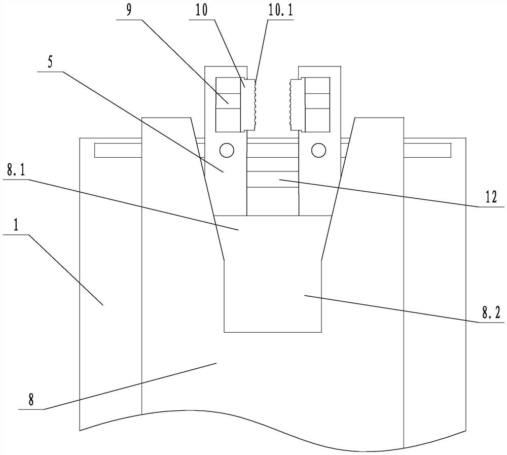
[0034] Such as figure 2 As shown, on the basis of Embodiment 1, the second driving mechanism 3 includes a second inclined push block 8, the second inclined push block 8 is fixed to the first inclined push block 6, and the second inclined push block 8 is provided with There are two second guide grooves 8.1 and two jaw blocks 5, one end of the jaw block 5 is hinged to the fixed frame 1, and the other end of the jaw block 5 is slidably connected to the corresponding second guide groove 8.1. The jaw block 5 is provided with a sliding column 11, which is slidingly connected with the second guide groove 8.1, and the jaw block 5 is slidingly connected with the second guide groove 8.1 through the sliding column 11. The jaw block 5 is provided with a compression spring 9 and a contact block 10, the contact block 10 is slidingly connected with the jaw block 5, one end of the compression spring 9 is connected with the jaw block 5, and the other end of the compression spring 9 is connect...


PUM


Abstract

The invention discloses a double-acting clamping jig with a shearing function. The double-acting clamping jig comprises a fixing frame, a first driving mechanism, a second driving mechanism, scissors, a clamping jaw block and a first inclined pushing block; and the first driving mechanism, the second driving mechanism and the scissors are arranged on the fixing frame, the clamping jaw block is arranged below the scissors, the first inclined pushing block is in sliding connection with the fixing frame, the first driving mechanism drives the first inclined pushing block to slide, a first guide groove is formed in the first inclined pushing block and is of a V-shaped structure, a large opening of the first guide groove faces the scissors, a handle of the scissors makes contact with the side wall of the first guide groove, and the second driving mechanism drives the clamping jaw block to move. According to the double-acting clamping jig with the shearing function, a material rod of an injection molding product is shorn, so that possible interference between the material rod and a punch of a punching machine due to deformation of the material rod is avoided, and further shortening of the injection molding period becomes reality.

Description

technical field [0001] The invention relates to the technical field of reclaiming jigs, in particular to a double-action clamping jig with a shearing function. Background technique [0002] The injection molding industry is a highly competitive industry, and the injection molding cycle is one of the most important parameters for cost control and production capacity control. If you can effectively reduce the injection molding cycle, you can win a competitive advantage. At present, the traditional method of reducing the cycle time does not involve the jig for taking the material. Generally, the mold is opened and clamped after the injection molded part is cooled. This method needs to wait for the product to be completely cooled and shaped before clamping, which cannot reduce the injection molding cycle to the greatest extent. If the product is clamped before it is completely cooled and shaped, the upper section of the material rod of the product will be deformed during clampi...

Claims


Application Information

Patent Timeline
Patent Type & Authority Applications(China)
IPC IPC(8): B29C45/17B26D7/02B26D1/30
CPCB29C45/1769B26D7/02B26D7/01B26D1/30B26D2007/013
Inventor 李振锋
Owner NINGBO BEILONG PRECISION MOLDING
Why Eureka
Try Eureka