
Spot ironing and punching device

A punching device and spot ironing technology, which is applied in metal processing, household components, household appliances, etc., can solve the problems of not being able to be neatly stacked, not paired, and waste, so as to achieve regular ironing and punching, and packaging Smooth box, stamping and ironing effects

Pending Publication Date: 2022-01-07
ZHANGJIAGANG PIONEER AUTOMATION MACHINERY EQUIP
View PDF0 Cites 2 Cited by
  • Summary
  • Abstract
  • Description
  • Claims
  • Application Information

AI Technical Summary

Problems solved by technology

During this process, due to the air left in the gloves, it is not very smooth to put the gloves into the packaging box, and they cannot be stacked neatly
Moreover, in the actual use process, no matter whether it is extracted from a napkin-like packaging box or opened for distribution, normal extraction or distribution cannot be guaranteed, and there will often be a situation where the final pair is not paired, resulting in unnecessary waste.

Method used


Image

  • Spot ironing and punching device
  • Spot ironing and punching device
  • Spot ironing and punching device

Examples


Embodiment 1

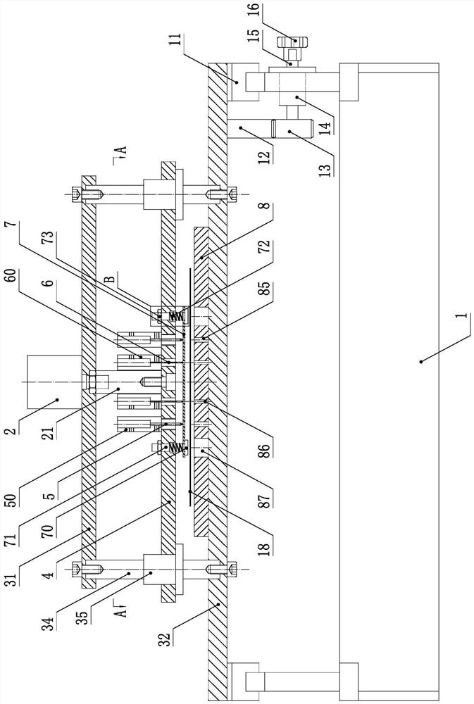
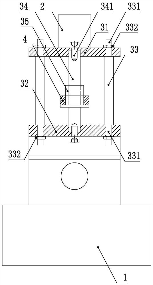
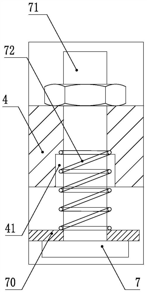
[0022] Such as figure 1 , figure 2 and Figure 4 As shown, a kind of ironing and punching device according to the present invention includes: a frame 1, on which a pair of linear bearings 11 parallel to each other is slidably provided with a lower fixing plate 32, and the lower fixing plate 32 is provided with a The mounting bracket, the specific structure of the mounting bracket includes: an upper fixing plate 31 positioned directly above the lower fixing plate 32 and parallel to the lower fixing plate 32, and four upper ends thereof are arranged in the upper fixing plate 31, The lower end is arranged on the fixed strut 33 in the lower fixed plate 32, and the upper and lower ends of the fixed strut 33 are respectively provided with a columnar extension 331 with a diameter smaller than its body, and the columnar extension 331 is provided with a threaded section. The upper and lower fixing plates 31 and 32 are provided with installation through holes that match the columnar ...

Embodiment 2

[0026] Such as Figure 5 As shown, another kind of spot ironing punching device described in the present invention, except that elastic pressing part wherein is different and needn't offer cap installation hole 87 on described working platform 8, all the other structures are identical. The elastic pressing member in the present embodiment comprises: the elastic soft pad 9 that is arranged on the back side of the slide plate 4, the elastic soft pad 9 is provided with punching pin via holes corresponding to all the punching pins 6 one-to-one, and is connected with all the thermal pads 6. Pin 5 has a one-to-one correspondence with thermal pin vias.


PUM


Abstract

The invention discloses a spot ironing and punching device which comprises a rack. A lower fixing plate is arranged on the rack; an installation support is arranged on the lower fixing plate; an air cylinder is arranged on the installation support; a sliding plate is movably arranged on the lower fixing plate through guide stand columns on the two sides; the sliding plate is connected with a piston rod of the air cylinder; at least two hot needle assemblies and at least one punching needle assembly are arranged on the sliding plate; each hot needle assembly comprises a hot needle seat arranged in the sliding plate and a hot needle arranged in the hot needle seat; the punching needle assembly comprises a punching needle seat arranged in the sliding plate and a punching needle arranged in the punching needle seat; a working platform is arranged on the lower fixing plate; a corresponding elastic pressing piece is arranged on the sliding plate; a punching needle via hole and a hot needle via hole which correspond to each other are formed in the elastic pressing piece; and a hot needle hole and a punching needle hole which correspond to each other are formed in the working platform. The spot ironing and punching device provided by the invention is mainly used as a glove packaging pretreatment device on a glove production line.

Description

technical field [0001] The invention relates to a pre-sorting device for glove packaging, in particular to a glove spot ironing and punching device. Background technique [0002] At present, when packaging gloves, it is usually just to put together a set number of gloves and then pack them into a box. During this process, due to the air left in the gloves, it is not very smooth to pack the gloves into the packing box, and they cannot be stacked neatly. Moreover, in actual use, no matter whether it is extracted from a napkin-like packaging box or opened for distribution, normal extraction or distribution cannot be guaranteed, and the final unpaired situation often occurs, thereby causing unnecessary waste. Contents of the invention [0003] The technical problem to be solved by the present invention is to provide a spot ironing and punching device that can make gloves paired and allow the gas in the gloves to be discharged smoothly when they are stacked. [0004] In order...

Claims


Application Information

Patent Timeline
Patent Type & Authority Applications(China)
IPC IPC(8): B29C65/74B29C65/18B26F1/24B29L31/48
CPCB29C65/74B29C65/18B29C65/7457B26F1/24B29C66/43B29C66/8242B29C66/83221B29C66/84B29L2031/4864
Inventor 朱国秋钱仁明
Owner ZHANGJIAGANG PIONEER AUTOMATION MACHINERY EQUIP
Learn More