Vertical axial flow pump

A technology of vertical shaft and pump shaft, which is applied to axial flow pumps, non-variable pumps, non-displacement pumps, etc., can solve the problems of consuming a lot of manpower, material resources, money, and inconvenient maintenance, and achieve large observation space, Ease of maintenance and minimal maintenance

Pending Publication Date: 2022-01-11
SHANGHAI LIANCHENG GRP SUZHOU
View PDF0 Cites 0 Cited by
  • Summary
  • Abstract
  • Description
  • Claims
  • Application Information

AI Technical Summary

Problems solved by technology

Such a maintenance method needs to consume a lot of manpower, material resources and money, and the maintenance is very inconvenient.

Method used


Image

  • Vertical axial flow pump
  • Vertical axial flow pump
  • Vertical axial flow pump

Examples


Embodiment Construction

[0030] The following will clearly and completely describe the technical solutions in the embodiments of the present invention with reference to the accompanying drawings in the embodiments of the present invention. Obviously, the described embodiments are only some, not all, embodiments of the present invention. Based on the embodiments of the present invention, all other embodiments obtained by persons of ordinary skill in the art without making creative efforts belong to the protection scope of the present invention.

[0031] In the description of the present invention, it should be noted that the orientation or positional relationship indicated by the terms "upper", "lower", "bottom", "inner" and "outer" are based on the orientation or positional relationship shown in the drawings , is only for the convenience of describing the present invention and simplifying the description, but does not indicate or imply that the referred device or element must have a specific orientatio...


PUM


Abstract

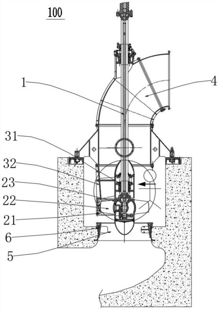
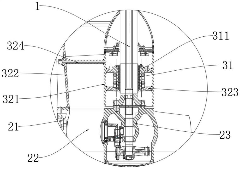
The invention discloses a vertical axial flow pump. The vertical axial flow pump comprises a pump shaft, wherein an impeller system and a guide vane body system are sequentially arranged from bottom to top in the axial direction of the pump shaft, and the guide vane body system comprises a water guide bearing arranged on the periphery of the pump shaft and a guide vane body arranged on the periphery of the water guide bearing; the guide vane body and the water guide bearing are both of a split structure; and the vertical axial flow pump has a detection state, and when the vertical axial flow pump is in the detection state, part of the guide vane body and part of the water guide bearing are installed on the pump shaft. Therefore, the corresponding position of the remaining guide vane body and the water guide bearing which are not installed provide detection space for installation personnel, and the installation personnel can directly observe the gap between the pump shaft and the water guide bearing from the front face at the positions where the guide vane body and the water guide bearing are not installed. The observation position is large in observation space and sufficient in light, so that observation is more convenient, and observation results are more accurate.

Description

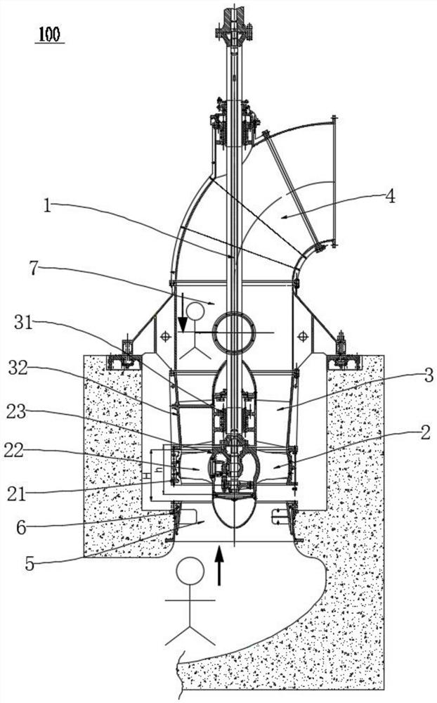
technical field [0001] The invention relates to a vertical axial flow pump. Background technique [0002] Large vertical axial flow pumps 100, such as figure 1 As shown, a pump shaft 1 is included, and an impeller system 2 , a vane body system 3 and an elbow 4 are sequentially arranged along the axial direction of the pump shaft 1 from bottom to top, and the pump shaft 1 runs through the vane body system 3 . The impeller system 2 includes an impeller casing 21, a rotor component 23 disposed in a cavity surrounded by the impeller casing 211, and an impeller 22 disposed on the outer periphery of the rotor component 23. The axis of the rotor component 23 is aligned with the The pump shaft 1 is on a straight line, the rotor part 23 is fixedly connected with the pump shaft 1; the vane body system 3 includes a water guide bearing 31 arranged on the outer periphery of the pump shaft 1, and is arranged on the The guide vane body 32 on the outer periphery of the water guide bearing...

Claims


Application Information

Patent Timeline
Patent Type & Authority Applications(China)
IPC IPC(8): F04D3/00F04D29/18F04D29/20F04D29/52F04D29/54F04D29/046F04D15/00F04D29/02F04D29/08F04D29/64
CPCF04D3/00F04D29/18F04D29/20F04D29/528F04D29/548F04D29/046F04D15/0088F04D29/026F04D29/086F04D29/648
Inventor 缪冬冬张锡淼
Owner SHANGHAI LIANCHENG GRP SUZHOU
Why Eureka
Try Eureka