
Battery, battery outgoing line method and electronic device

A technology of batteries and batteries, which is applied in the field of battery outlets, electronic devices, and batteries, and can solve problems such as circuit board damage, lack of mobility, and impact on batteries

Pending Publication Date: 2022-01-11
DONGGUAN NVT TECH
View PDF3 Cites 0 Cited by
  • Summary
  • Abstract
  • Description
  • Claims
  • Application Information

AI Technical Summary

Problems solved by technology

Among them, the outlet method of the battery cell greatly affects the reliability of the assembly and connection of the battery in the finished chassis. In order to increase the safety performance of the battery cell, the battery cell will be placed in a plastic frame and filled with melted plastic by injection molding. The battery core forms a solid body to protect the battery core. After injection molding, the circuit board is fixed by injection molding melt in the plastic frame, so that the circuit board may be damaged during the packaging process of the battery core. At the same time, it is connected to the circuit board. Due to the lack of mobility of the circuit board, which is fixed by injection molding glue, there is a risk of being pulled off
In this way, hidden dangers are buried for the safety performance of the battery cell

Method used


Image

  • Battery, battery outgoing line method and electronic device
  • Battery, battery outgoing line method and electronic device
  • Battery, battery outgoing line method and electronic device

Examples


no. 1 example

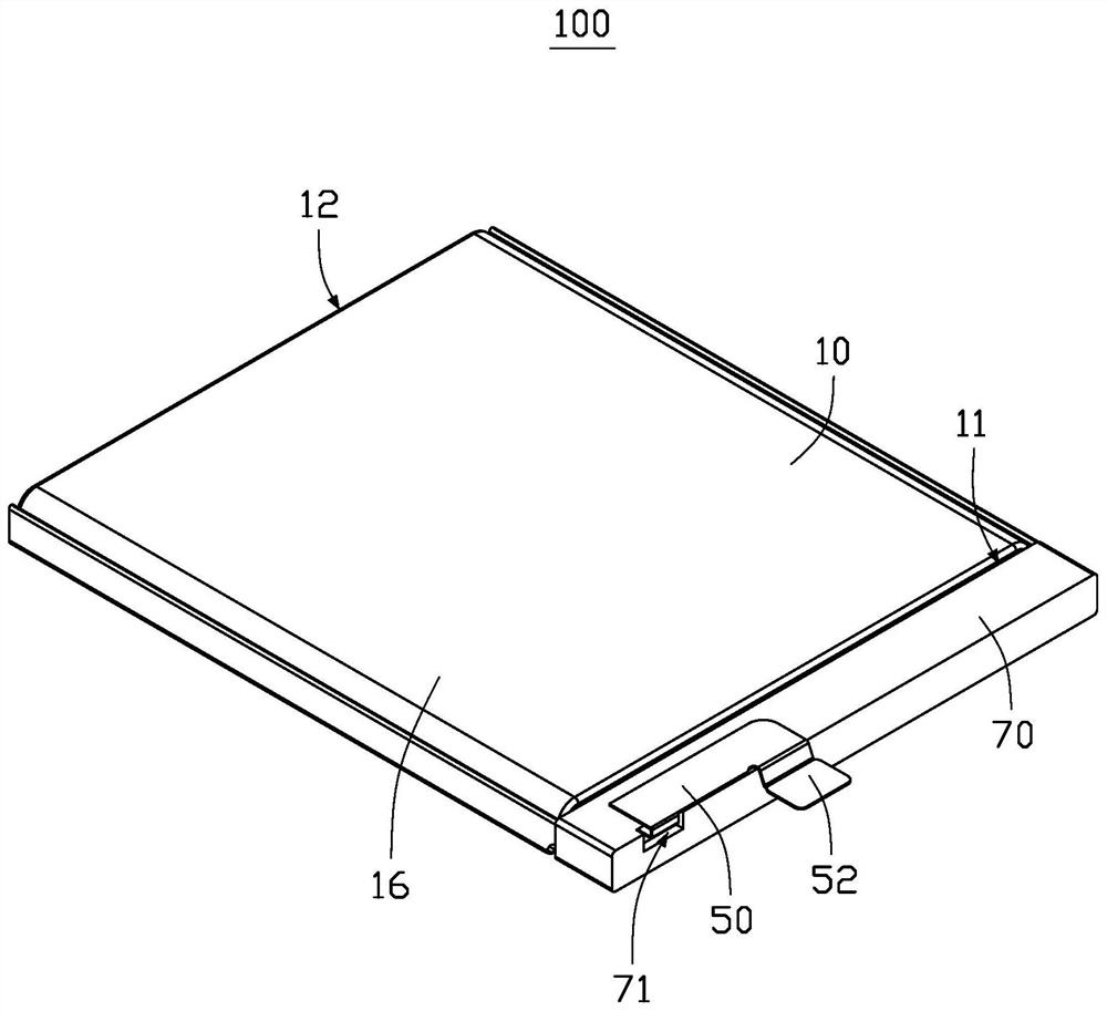
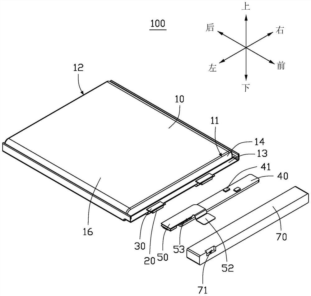
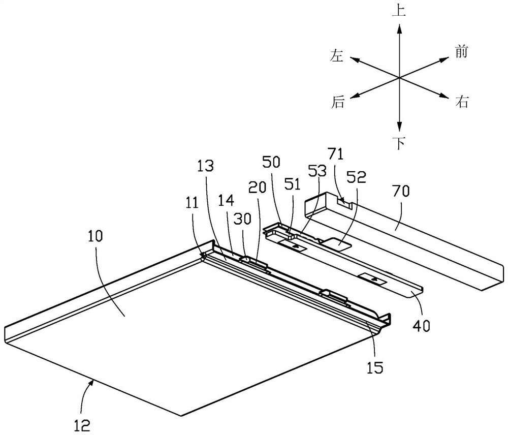
[0068] see figure 1 and figure 2 , providing a battery 100 for providing electric energy to an electronic device. The battery 100 includes a cell body 10 , a circuit board 40 , a first connector 50 and a gel 70 , and the cell body 10 includes a first side 11 provided with a tab 20 along the length direction and a side 11 away from the tab 20 . 12 of the second side. The circuit board 40 is electrically connected to the tab 20 . The first connecting member 50 includes a first end portion 51, a second end portion 52 and a first bending portion 53 connecting the first end portion 51 and the second end portion 52, the first end portion 51 is electrically connected to the circuit board 40, and the second end 52 is used for connecting external devices. The glue 70 is disposed on the first side 11 and covers the tab 20 , the circuit board 40 and the first end 51 . The first bent portion 53 extends along the surface of the glue 70 , and the second end portion 52 extends out of t...

no. 2 example

[0104] see Figure 5 and Figure 6 , in the second embodiment, the battery 100 is substantially the same as that in the first embodiment, the difference is that the second end portion 52 extends from the first side 11 to a direction close to the second side 12 . When the first connecting member 50 extends toward the second side 12 and passes through the stepped surface formed by the cell body 10 and the glue 70 , the first bent portion 53 is along the stepped surface. It is bent and extends toward the second side 12 along the side wall 16 of the cell body 10 .

[0105] The first connecting member 50 extends out of the cell body 10 from the first side 11 to the second side 12 to connect with external equipment, which can also achieve the same effect as in the first embodiment.

no. 3 example

[0107] see Figure 7 and Figure 8 , in the third embodiment, the battery 100 is substantially the same as that in the first embodiment, the difference is that the battery 100 further includes a second connector 60, and the second connector 60 includes a third end 61, a second The four end portions 62 and the second bending portion 63 connecting the third end portion 61 and the fourth end portion 62 . The third end portion 61 is electrically connected to the circuit board 40 , the second bent portion 63 extends along the surface of the glue 70 , and the fourth end portion 62 is along the length direction of the cell body 10 or The colloid 70 extending in the width direction is connected with external equipment.

[0108] Specifically, the third end 61 is connected to the circuit board 40 , the connection between the third end 61 and the circuit board 40 is the same as the connection between the first end 51 and the circuit board 40 the same way. The second connecting piece ...


PUM


Abstract

The invention provides a battery. The battery comprises a battery cell body, a circuit board, a first connecting piece and colloid, the battery cell body comprises a first side provided with a tab and a second side away from the tab in the length direction, the circuit board is electrically connected to the tab, and the first connecting piece comprises a first end part, a second end part and a first bending part connecting the first end part and the second end part; and the first end part is electrically connected to the circuit board, the second end part is used for being connected with external equipment, the colloid is arranged on the first side and wraps the tab, the circuit board and the first end part, the first bending part extends along the surface of the colloid, and the second end part extends out of the colloid from the length direction or the width direction of the cell body. The invention further relates to a wire outlet method of the battery and an electronic device adopting the battery, by adopting the battery, the overall process and cost of the battery can be simplified, and the safety and reliability of the battery can be improved.

Description

technical field [0001] The present application relates to the technical field of batteries, and in particular to a battery, a battery outlet method, and an electronic device. Background technique [0002] In the field of traditional soft-pack lithium batteries, battery packaging has always been a major problem facing the industry, especially for large-capacity lithium battery products developed in recent years. The design and manufacture of the core presents challenges. Among them, the outlet method of the battery cell greatly affects the reliability of the assembly and connection of the battery in the finished chassis. In order to increase the safety performance of the battery cell, the battery cell will be placed in a plastic frame and filled with melted plastic by injection molding. The battery core forms a solid body to protect the battery core. After injection molding, the circuit board is fixed by injection molding melt in the plastic frame, so that the circuit board ...

Claims


Application Information

Patent Timeline
Patent Type & Authority Applications(China)
IPC IPC(8): H01M50/528H01M50/533H01M50/572H01M10/052
CPCH01M10/052Y02E60/10
Inventor 姚明高
Owner DONGGUAN NVT TECH
Learn More