
Power terminal and connector assembly

A combination technology of power terminals and connectors, which is applied in the direction of connection, contact parts, electrical components, etc., can solve problems such as insufficient buffering of soldering parts, tin cracks, and affecting the electrical connection of electrical connectors

Active Publication Date: 2021-04-23
DEYI PRECISION ELECTRONIC IND CO LTD PANYU
View PDF6 Cites 0 Cited by
  • Summary
  • Abstract
  • Description
  • Claims
  • Application Information

AI Technical Summary

Problems solved by technology

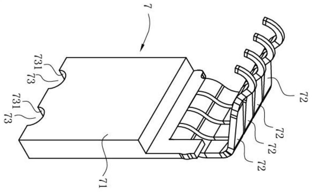
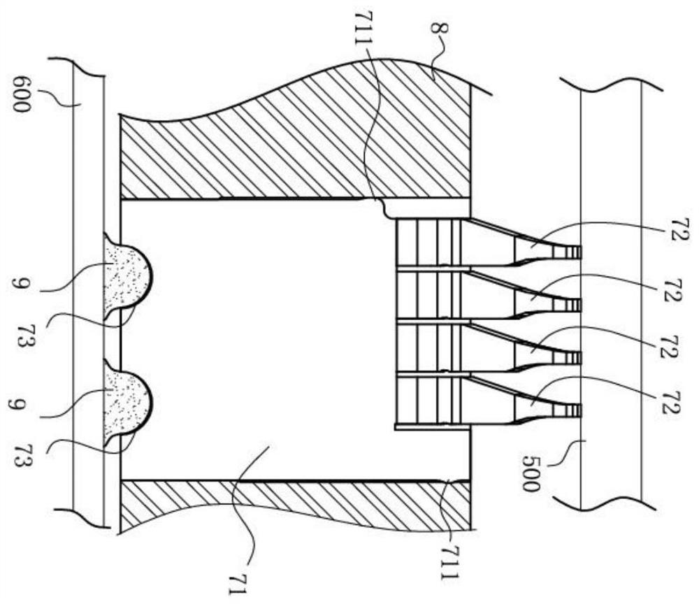
However, when the electrical connector is welded on the circuit board 600 and the insulating body 8 is deformed, the conductive terminal 7 will be pulled due to the deformation of the insulating body 8. Since there is not enough space for the conductive terminal 7 to undergo sufficient elastic deformation, it is not enough Buffer the pulling force on the soldering part, so that the soldering part is pulled and moved, which is easy to cause tin cracking, thus affecting the normal electrical connection of the electrical connector

Method used


Image

  • Power terminal and connector assembly
  • Power terminal and connector assembly
  • Power terminal and connector assembly

Examples


Embodiment Construction

[0032] In order to facilitate a better understanding of the purpose, structure, features, and effects of the present invention, the present invention will now be further described in conjunction with the accompanying drawings and specific embodiments.

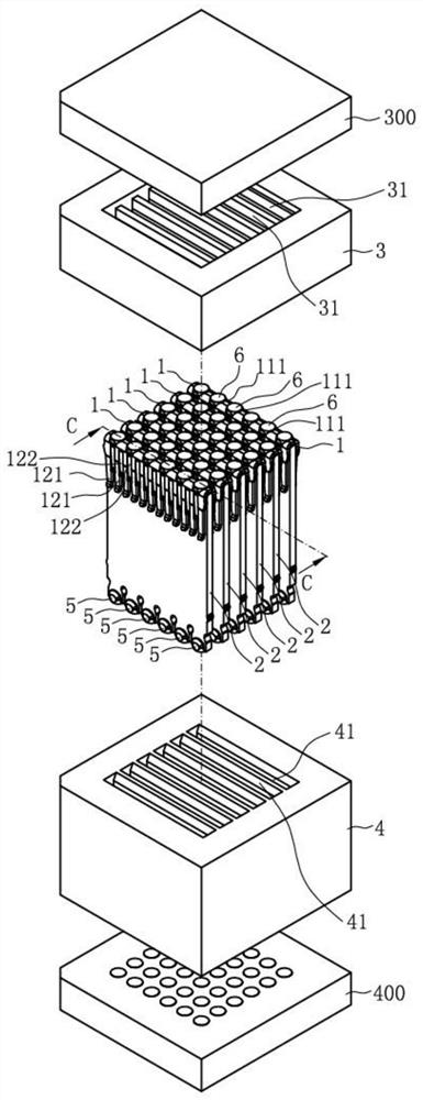
[0033] Such as Figure 3 to Figure 11 Shown is an embodiment of the connector assembly of the present invention, the connector assembly is used to electrically connect an upper circuit board 300 to the lower circuit board 400, the connector assembly includes a soldered on the upper circuit board 300 Docking the electrical connector 100 and an electrical connector 200 welded on the lower circuit board 400, the electrical connector 200 includes a lower insulating body 4 and a terminal 2 accommodated in the lower insulating body 4, the terminal 2 can One, two, three or even more; the butt electrical connector 100 includes an upper insulating body 3 and a plurality of butt terminals 1 disposed on the upper insulating body 3 . Of c...


PUM


Abstract

The present invention provides a power terminal and connector assembly, comprising: a base portion, a plurality of elastic portions extending downward from the base portion side by side along the left and right directions, and extending downward from each elastic portion to form a welding portion, the welding The bottom part is provided with a groove upwards from its bottom surface, and the groove has left and right opposite side walls to clamp a solder ball together, a horizontal center line of the solder ball passes through the two side walls, and two adjacent An elastic deformation space is formed between the elastic parts; for the power supply terminal, there is an elastic deformation space between adjacent elastic parts in the present invention, and the elastic deformation of the elastic part can effectively relieve the pulling force on the terminal, so that the welding part is not pulled Keeping the soldering part still can reduce the force on the solder ball and avoid tin cracking.

Description

【Technical field】 [0001] The invention relates to a terminal and a connector assembly, in particular to a power terminal and a connector assembly capable of preventing tin cracking. 【Background technique】 [0002] Such as figure 1 , figure 2 The disclosed conductive terminal 7 has a main body portion 71 in the form of a flat plate. Fixing portions 711 are provided on the left and right sides of the main body portion 71 to fix the conductive terminal 7 to the insulating body 8, and extend upwards from the main body portion 71. A plurality of elastic arms 72 are arranged in a row along the left and right directions, and the top of the elastic arms 72 abuts against a chip module 500 upwards, and a plurality of grooves 73 are recessed upwards on the bottom surface of the main body 71 and arranged side by side along the left and right directions. The groove 73 has left and right opposite side walls 731 to clamp the solder 9 together, so as to solder the conductive terminal 7 t...

Claims


Application Information

Patent Timeline
Patent Type & Authority Patents(China)
IPC IPC(8): H01R13/24H01R24/00
CPCH01R13/24H01R24/00
Inventor 黄常伟
Owner DEYI PRECISION ELECTRONIC IND CO LTD PANYU
Learn More