
Combined hydraulic cylinder with floating cylinder body

A combined, hydraulic cylinder technology, applied in the hydraulic field, can solve the problems of large pulling force, destructiveness, and damaged conduits, and achieve the effects of alleviating the pulling force, not easy to crack, and easy to repair and replace.

Pending Publication Date: 2022-05-03
何福有
View PDF0 Cites 0 Cited by
  • Summary
  • Abstract
  • Description
  • Claims
  • Application Information

AI Technical Summary

Problems solved by technology

[0004] Aiming at the deficiencies of the prior art, the present invention provides a combined hydraulic cylinder with a floating cylinder body, which solves the problem that the hydraulic cylinder piston and the cylinder head will mechanically collide without decelerating the movement of the hydraulic cylinder, resulting in impact, noise, and damage. At the same time, the pulling force is too large, which will pull the catheter connected to the outside world, resulting in damage to the catheter

Method used


Image

  • Combined hydraulic cylinder with floating cylinder body
  • Combined hydraulic cylinder with floating cylinder body
  • Combined hydraulic cylinder with floating cylinder body

Examples


Embodiment 1

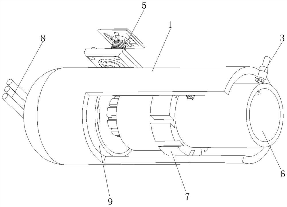
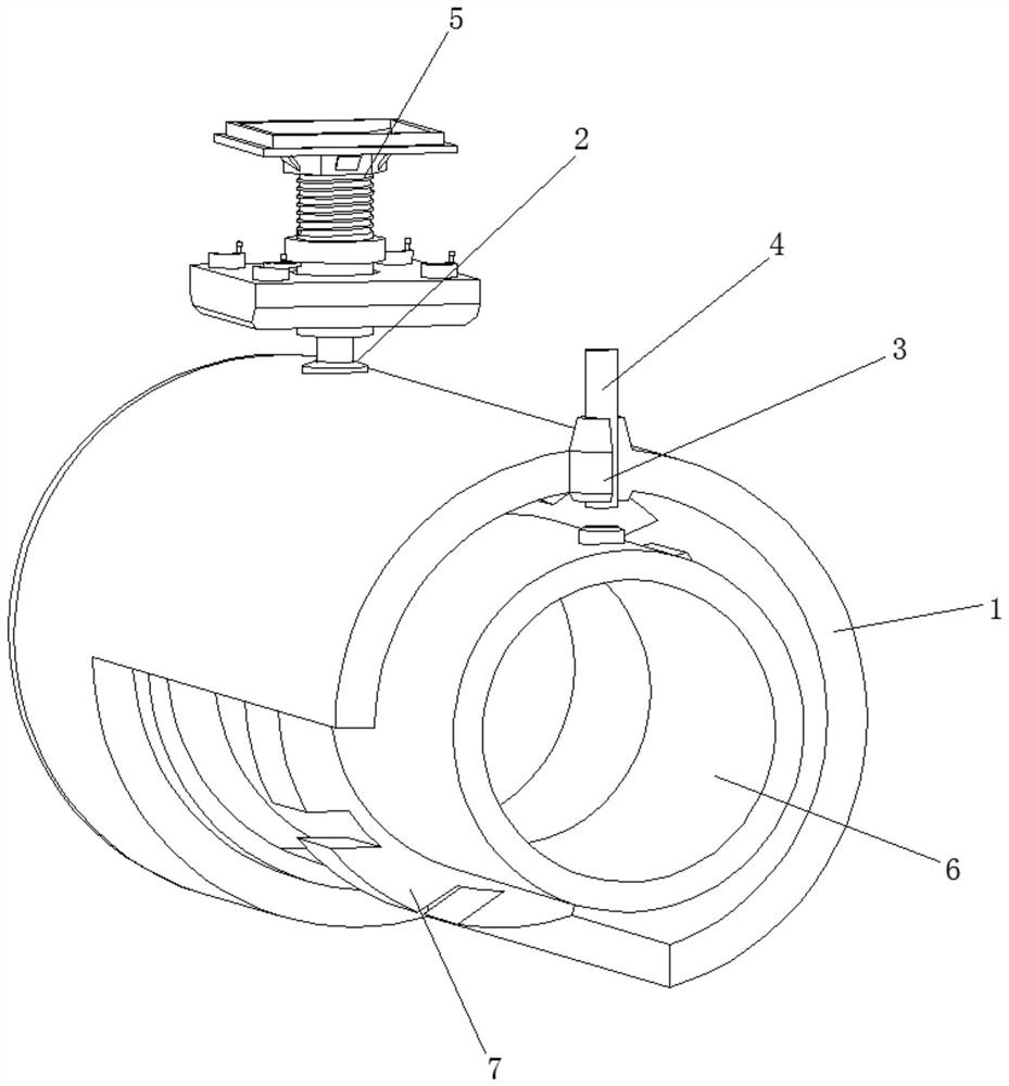
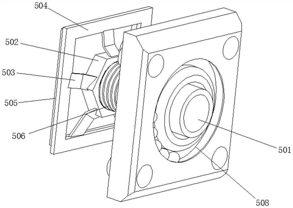
[0031] see Figure 1-6 , the present invention provides a technical solution: a combined hydraulic cylinder with a floating cylinder body, including a hydraulic housing 1, a circular groove 2 is opened on the left and right sides of the top of the hydraulic housing 1, and the inner surface of the circular groove 2 is fixedly connected There is an anti-leakage ring 3, the inner surface of the anti-leakage ring 3 is fixedly connected with a conduit 4, the outer surface of the conduit 4 is movably connected with a buffer mechanism 5, the inner surface of the hydraulic housing 1 is slidably connected with a sliding cavity 6, the sliding cavity 6 The outer surface is provided with an anti-skid mechanism 7, the left side of the hydraulic housing 1 is connected with a frame tube 8 through a fixed cylinder, and the left side of the inner surface of the hydraulic housing 1 is fixedly connected with an anti-collision ring 9; when the hydraulic cylinder has a large kinetic energy, Both t...

Embodiment 2

[0042] see Figure 7 , the present invention provides a technical solution: the anti-slip mechanism 7 includes a circular hole 701, the inner surface of the anti-collision ring 9 is fixedly connected with the outer surface of the circular hole 701, and the inner surface of the circular hole 701 is fixedly connected with the outer surface of the left conduit 4, The outer surface of the sliding cavity 6 is fixedly connected with an anti-slip ring 702 , the outer surface of the anti-slip ring 702 is slidably connected with the inner surface of the hydraulic housing 1 , and the outer surface of the sliding cavity 6 is rotatably connected with a driving wheel 703 . After the hydraulic housing 1 enters the liquid, it is impacted by the liquid, and the driving wheel 703 rotates, which will also accelerate the speed of the liquid entering the hydraulic housing 1, and at the same time accelerate the reciprocating speed of the entire hydraulic cylinder, and cooperate with the internal an...


PUM


Abstract

The invention discloses a combined hydraulic cylinder with a floating cylinder body, and relates to the technical field of hydraulic pressure. The combined hydraulic cylinder with the floating cylinder body comprises a hydraulic shell, circular grooves are formed in the left side and the right side of the top of the hydraulic shell, anti-leakage rings are fixedly connected to the inner surfaces of the circular grooves, guide pipes are fixedly connected to the inner surfaces of the anti-leakage rings, and buffer mechanisms are movably connected to the outer surfaces of the guide pipes. Some combined connecting parts convenient to disassemble and assemble are additionally arranged inside and outside the hydraulic cylinder, accessories are used when the hydraulic cylinder is used, and when pressure is converted into power, an anti-skid mechanism and a buffering mechanism are used in cooperation, and when the hydraulic cylinder has large kinetic energy, the anti-skid mechanism and the buffering mechanism are used in a matched mode; the guide pipe and the inner sliding cavity are protected and decelerated, the situation that due to too large impact force, the inner abraded guide pipe is damaged due to too large pulling force is prevented, the buffer mechanism and the guide pipe can be taken down at will, and maintenance and replacement are convenient.

Description

technical field [0001] The invention relates to the field of hydraulic technology, in particular to a combined hydraulic cylinder with a floating cylinder body. Background technique [0002] A hydraulic cylinder is a hydraulic actuator that converts hydraulic energy into mechanical energy and performs linear reciprocating motion (or swing motion). It has simple structure and reliable operation. When it is used to realize reciprocating motion, the deceleration device can be eliminated, and there is no transmission gap, and the motion is stable, so it is widely used in various mechanical hydraulic systems. The output force of the hydraulic cylinder is proportional to the effective area of ​​the piston and the pressure difference on both sides; the hydraulic cylinder is basically composed of a cylinder barrel and a cylinder head, a piston and a piston rod, a sealing device, a buffer device and an exhaust device. [0003] The gas is compressed by the piston in the compressor c...

Claims


Application Information

Patent Timeline
Patent Type & Authority Applications(China)
IPC IPC(8): F15B15/14F15B15/20
CPCF15B15/1423F15B2215/30
Inventor 何福有
Owner 何福有
Learn More