

Lifting auxiliary device and lifting operation method of part to be operated
An auxiliary device and operation technology, applied in the direction of portable lifting device, winch device, etc., to achieve the effect of wide adaptability, convenient disassembly and installation, and convenient operation
- Summary
- Abstract
- Description
- Claims
- Application Information
AI Technical Summary
Problems solved by technology
Method used
Image

Examples
Embodiment 1
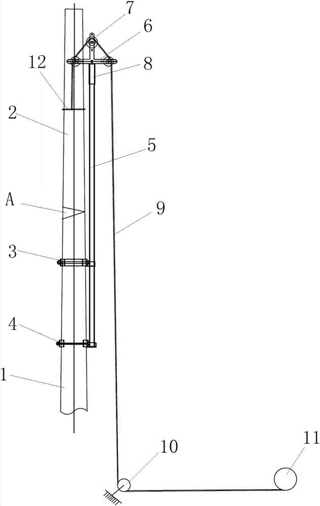
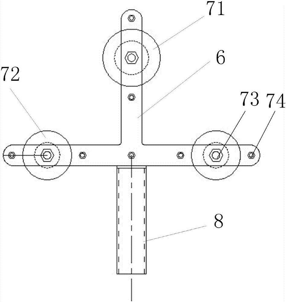
[0078] Such as figure 1 and figure 2 As shown, a lifting auxiliary device is used to cooperate with the driving mechanism 11 and the steel wire rope 9. The steel wire rope 9 is connected to the part 2 to be operated, so that the part 2 to be operated can be lifted or lowered on the main body 1 to be operated. The auxiliary device for lifting includes Holding mechanism, support frame and pulley assembly 7; wherein, holding mechanism is installed on the main body 1 to be operated, is used for supporting support frame and preventing support frame from toppling over; Support frame is vertically supported on the holding mechanism, uses It is used to support the pulley assembly 7; the pulley assembly 7 is installed on the top of the support frame, and is used to support the steel wire rope 9 and change direction when the steel wire rope 9 walks around.
[0079] When in use, the lifting auxiliary device is installed on the main body 1 to be operated, the steel wire rope 9 is connec...
other Embodiment approach
[0086] In other embodiments, the clamping diameters of the upper clamping device 3 and the lower clamping device 4 are fixed, and can only be adapted to a cylindrical body of one size. It can also be used in the upper clamping device 3 and the lower clamping device 4, one clamping diameter is fixed, the other clamping diameter is adjustable, or both clamping diameters can be adjusted, then it can adapt to cylindrical bodies of different sizes, thus Only one clamping device is needed to complete the operation of various sizes of cylindrical main bodies, which improves work efficiency and saves multiple sets of clamping devices; the clamping diameter range is adjustable, which can effectively adapt to pull-out poles of different diameters , Easy to disassemble and install.
[0087] Another aspect of the present invention is to provide a lifting operation method of the component 2 to be operated:
[0088] First install the auxiliary support device with the pulley assembly 7 on t...
Embodiment 2
[0097] Embodiment 2 is basically the same as Embodiment 1, the difference lies in that the locking parts of the upper clamping device 3 and the lower clamping device 4 are adjusted in different ways.
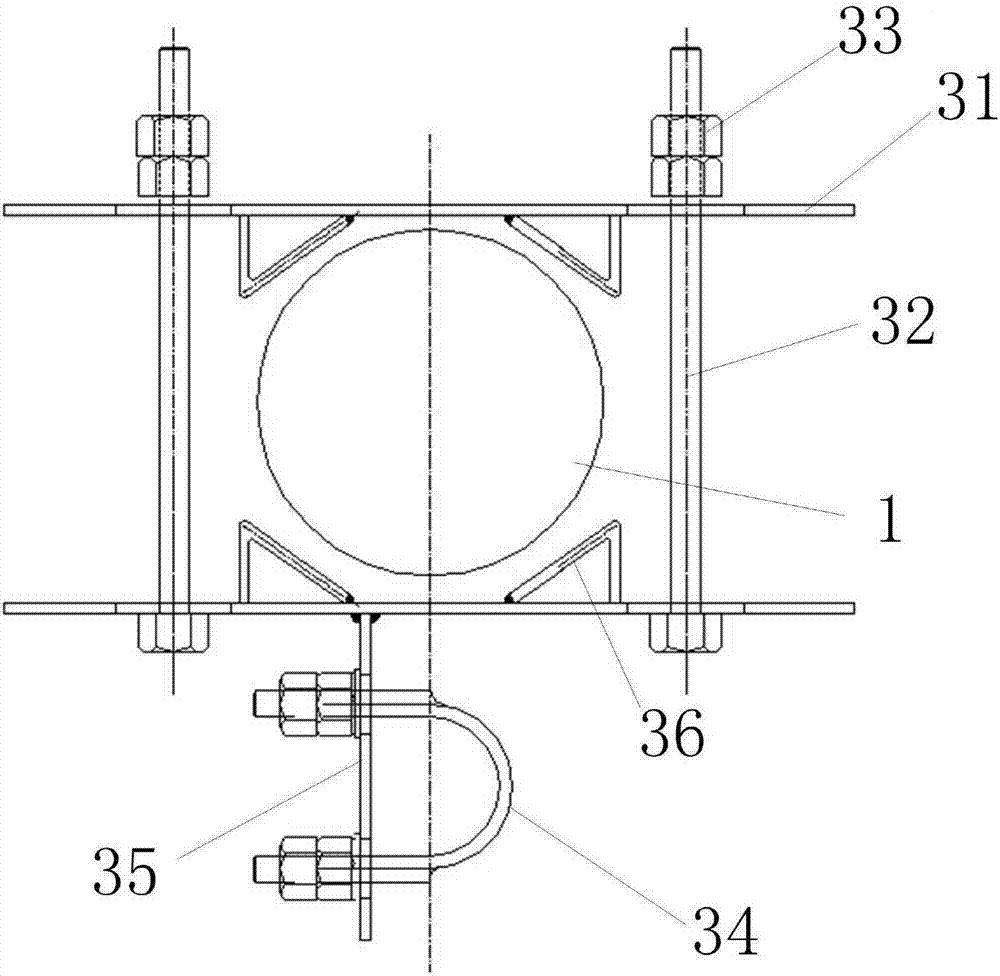
[0098] Such as Figure 6 to Figure 10 As shown, the locking member includes two supporting plates 31 oppositely arranged and two adjusting bolts 32 vertically connected between the two supporting plates 31, two supporting assemblies 38 are respectively arranged inside the two supporting plates 31, four The supportable component 38 is symmetrically arranged on the two support plates 31 relative to the midpoint of the pole, that is, the clamping force on the pole is relatively balanced to avoid twisting due to bending moment, and the state of the pole's hoop is stable. The radial position of the support assembly 38 on the two support plates 31 is adjustable; or the radial position of the support assembly 38 on one support plate 31 is fixed, and the radial position of the support a...
PUM
 Abstract
Description
Claims
Application Information