
Steering tube type electric power assisting device

A steering column and electric power assist technology, applied in steering mechanism, electric steering mechanism, power steering mechanism, etc., can solve the problems of difficult installation and disassembly, affecting the output torque, occupying a large space, etc., and achieving flexible steering operation. , The effect of increasing the output torque and taking up less space

Inactive Publication Date: 2016-06-22
毕大宁
View PDF6 Cites 4 Cited by
  • Summary
  • Abstract
  • Description
  • Claims
  • Application Information

AI Technical Summary

Problems solved by technology

[0002] At present, the electric power steering system used in various vehicles is mostly realized by installing a worm gear reduction device on the steering column. This type of structure is limited by its own size, the transmission ratio is relatively low, and the transmission efficiency is low, which directly affects the output torque. the size of
Since it needs to be installed on the side of the steering column together with the external motor, it takes up a lot of space. Since there are various assemblies and components distributed under the vehicle instrument panel, the steering column and peripheral components of the existing vehicle are assembled and maintained. Frequent interference, difficult installation and removal operations

Method used


Image

  • Steering tube type electric power assisting device
  • Steering tube type electric power assisting device
  • Steering tube type electric power assisting device

Examples


Embodiment Construction

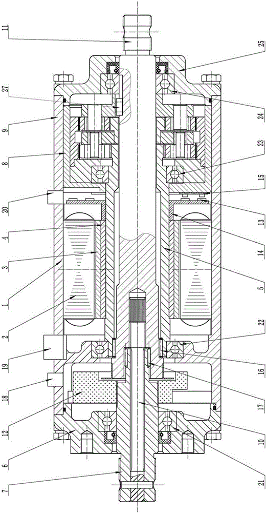
[0011] A new type of steering column type electric power booster according to the present invention includes a housing 1, which is integrated with a diaphragm, and a torque angle sensor 12 is installed on one side of the diaphragm input shaft 7 of the housing 1, and a hollow type sensor 12 is installed in the middle. The inner rotor brushless motor, the planetary gear reducer 8 is installed on the side of the output shaft 11 of the casing 1. The coil stator 2 of the hollow inner rotor brushless motor is fixedly connected with the inner wall of the housing 1, and the magnetic steel rotor 3 is fixedly installed on the outside of the sleeve 4, and the sleeve 4 is fixedly installed on the sleeve shaft 5, and one end of the sleeve shaft 5 passes through The second positioning bearing 22 is connected with the diaphragm, and the other end of the sleeve shaft 5 is positioned and connected with the planetary gear reducer 8 through the third positioning bearing 23. The lower end of the s...


PUM


Abstract

A steering tube type electric power assisting device comprises a shell. A planetary gear reducer is mounted at one end of the shell. A transverse partition board is arranged in the shell. A hollow internal rotor brushless motor is mounted in the shell and located between the transverse partition board and the planetary gear reducer. A coil stator of the hollow internal rotor brushless motor is connected with the inner wall of the shell. A shaft sleeve is arranged in a center inner hole of a magnetic steel rotor of the hollow internal rotor brushless motor. The shaft sleeve is fixedly mounted on a sleeve shaft. One end of the sleeve shaft is connected with the transverse partition board of the shell through a first location bearing. According to the steering tube type electric power assisting device, the hollow internal rotor brushless motor and the planetary gear reducer are arranged coaxially with a steering tube, so that the steering tube type electric power assisting device occupies small space, does not interfere with peripheral components, can be easily arranged on a car and is easy and convenient to dismount, mount and operate. During motor running, torque of the motor is amplified through the planetary gear reducer, and the rotational speed of the motor is decreased through the planetary gear reducer, so that the effect of power assistance is achieved. The mechanical transmission efficiency is substantially improved, and the steering tube type electric power assisting device can make steering operation of the car more flexible, easier, more stably and the like.

Description

technical field [0001] The invention relates to an automobile steering device, in particular to a steering column type electric power booster. Background technique [0002] At present, the electric power steering system used in various vehicles is mostly realized by installing a worm gear reduction device on the steering column. This type of structure is limited by its own size, the transmission ratio is relatively low, and the transmission efficiency is low, which directly affects the output torque. the size of. Since it needs to be installed on the side of the steering column together with the external motor, it takes up a lot of space. Since there are various assemblies and components distributed under the vehicle instrument panel, the steering column and peripheral components of the existing vehicle are assembled and maintained. Interference occurs frequently, and installation and removal operations are difficult. Contents of the invention [0003] The purpose of the...

Claims


Application Information

Patent Timeline
IPC IPC(8): B62D5/04
CPCB62D5/0415B62D5/0442
Inventor 毕大宁
Owner 毕大宁
Learn More