Pavement repairing device for concrete road maintenance

A technology for road maintenance and pavement repair, which is applied in road repair, roads, roads, etc. It can solve the problems of repeated construction injection, poor effect, waste of road repair agent and complicated cleaning, and achieve the effect of prolonging the polymerization time and improving the repair effect

Inactive Publication Date: 2022-01-14
东营职业学院
View PDF0 Cites 2 Cited by
  • Summary
  • Abstract
  • Description
  • Claims
  • Application Information

AI Technical Summary

Problems solved by technology

[0006] In order to overcome the shortcomings of poor one-time pouring effect when repairing cracks by the direct pouring method on highways, repeated construction pouring, indeterminate crack shape, complicated construction, and waste of road surface repairing agent, the technical problem of the present invention is to provide a Accurate positioning, pressurized pouring and pavement repair agent pavement margin control, realize the concrete road maintenance pavement repair device that moves along the road crack and completes pouring at one time

Method used


Image

  • Pavement repairing device for concrete road maintenance
  • Pavement repairing device for concrete road maintenance
  • Pavement repairing device for concrete road maintenance

Examples


Embodiment 1

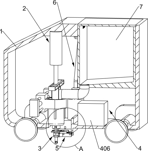
[0032] A road surface patching device for concrete road maintenance, such as figure 1 and figure 2 As shown, it includes an electric trolley 1, a perfusion device 2, a positioning device 3 and an information processing module 4. The electric trolley 1 is placed above the road cracks, and cooperates with its internal device to complete the repair of the road cracks. The electric trolley 1 is fixed There are perfusion device 2 and positioning device 3. There is a through hole on the left part of the lower surface of the electric trolley 1, which is used for protruding and recovering the perfusion device 2 and positioning device 3. There is a through hole on the right part of the upper surface of the electric trolley 1. The electric trolley 1. There are mounting plates on the front and rear sides around the opening on the lower surface. There are mounting plates symmetrically arranged up and down on the right side of the opening on the lower surface of electric trolley 1. Two ch...

Embodiment 2

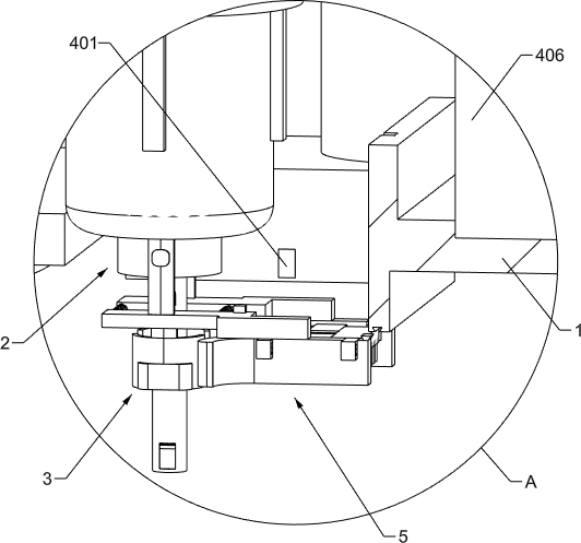
[0041] On the basis of Example 1, such as Figure 8 and Figure 9 As shown, a margin adjustment device 5 is also included, and the margin adjustment device 5 is fixedly connected to the positioning device 3. The margin adjustment device 5 includes a bending baffle 501, a trapezoidal slider 502, a trapezoidal limit block 503, a trapezoidal The connection block 504, the first brush seat 505, the second brush seat 506, the third brush seat 507, the third spring 508 and the bristles 509, the bending baffle plate 501 and the trapezoidal slide block 502 are respectively provided with two front and rear symmetrical The middle part of the upper surface of the bent baffle 501 is respectively fixed on the lower surface of the right part of the Z-shaped connecting block 306. Each bent baffle 501 is provided with two placement grooves and the upper surface of the right part is fixed with a trapezoidal slider 502. The folding baffle 501 is close to the ground and its left end is outwardly...


PUM


Abstract

The invention relates to the field of road maintenance, in particular to a pavement repairing device for concrete road maintenance. The invention relates to a pavement repairing device for concrete road maintenance, which can move along a road crack to complete pouring at one time through accurate positioning, pressurized pouring and pavement allowance control of a pavement repairing agent. A pavement repairing device for concrete road maintenance comprises an electric trolley, a pouring device, a positioning device, an information processing module and the like. The filling device, the positioning device and the information processing module are fixedly connected in the electric trolley. The effects achieved by the invention are as follows: the electric trolley bears the pouring device and the positioning device to realize crack repair in the moving process, the pouring device is matched with the positioning device, the pouring device is positioned in the crack through the positioning device, and the pouring device moves along with the change of the direction of the crack; and the pouring device achieves one-time pouring of the pavement repairing agent through pressure pouring.

Description

technical field [0001] The invention relates to the field of road maintenance, in particular to a road surface repairing device for concrete road maintenance. Background technique [0002] Since the reform and opening up, my country's economy has developed rapidly. Among all walks of life, the highway industry, as a pillar industry in the transportation industry, is playing an increasingly important role; among the early diseases of the road surface, cracks are the most serious category. It has seriously damaged the driving safety, affected the development of the transportation industry, and slowed down the development rate of my country's economy. Therefore, in order to reduce the continuous damage to the road surface, timely repair and maintenance of road cracks has become a very necessary technology. . [0003] The reasons for the formation of cracks include: severe overloading, severe temperature changes, and imperfect drainage facilities. According to the damage form, cr...

Claims


Application Information

Patent Timeline
Patent Type & Authority Applications(China)
IPC IPC(8): E01C23/09
CPCE01C23/096E01C23/0973
Inventor 庞兰霞
Owner 东营职业学院
Why Eureka
Try Eureka