Automatic timing sports stopwatch
A technology of automatic timing and movement, applied in the field of sports stopwatches, can solve the problems of long preparation work, inconvenient application, and accuracy dependence, etc., and achieve the effect of improving unfolding and folding, increasing service life, and improving convenience
- Summary
- Abstract
- Description
- Claims
- Application Information
AI Technical Summary
Problems solved by technology
Method used
Image
Examples
Embodiment 1
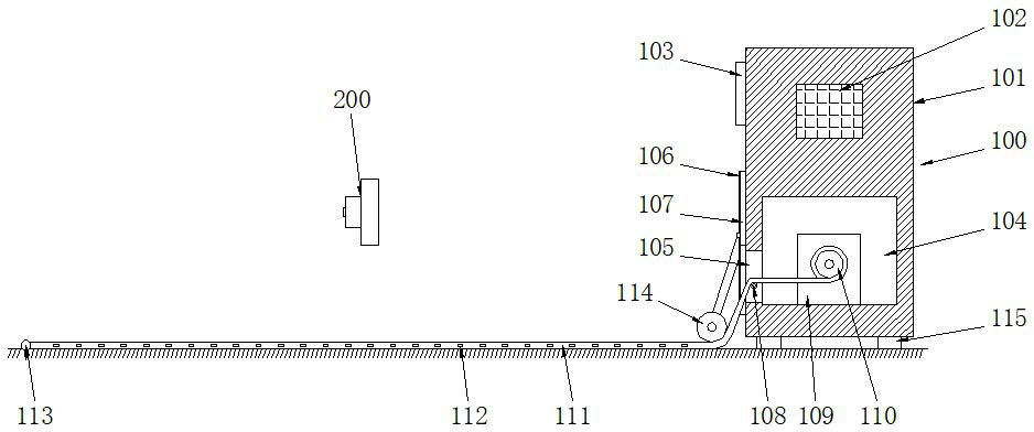
[0033]See Figure 1-2 , a sports stopwatch for automatic timing, including a number of identification cards 200 and an identification recording device 100 matched with the identification cards 200, the identification recording device 100 includes a base case 101, the bottom of the base case 101 is uniform A number of legs 115 are provided, and the base case 101 is supported by the legs 115, so as to ensure the stability of the whole device in use;
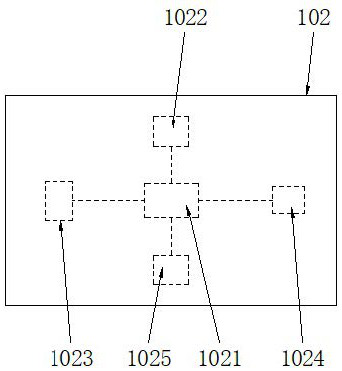
[0034] The base box 101 is provided with a timing control board 102 and a sealing chamber 104, the sealing chamber 104 is arranged under the timing control board 102, the side end of the sealing chamber 104 is connected to the control window 105, and the inner cavity bottom of the sealing chamber 104 A winding motor 109 is fixedly connected to the wall, and the winding motor 109 is rotated and connected with a winding roller 110, and the winding roller 110 is wound with a stepping cloth 111 matched with the control window 105, and ...
Embodiment 2
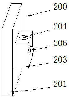
[0039] See Figure 3-4 The difference from Embodiment 1 is that the identity card 200 includes a base card 201, the base card 201 is embedded with an identity chip 202, and one end of the base card 201 is fixedly connected to the mounting seat 203, and the base card 201 is connected to the installation The seats 203 are integrally formed, and the mounting seat 203 is provided with a wire hole 204, the wire hole 204 connects the upper and lower end surfaces of the mounting seat 203, and one side end of the wire hole 204 connects with the fastening hole 205, The relationship between the thread hole 204 and the fastening hole 205 is perpendicular to each other. The thread hole 204 is internally threaded with a fastening bolt 206 matched with the thread hole 204. The shoelace passes through the thread hole 204 and is matched with the fastening bolt 206. The fastening hole 205 securely installs the mounting base 203 on the carrier, so that the base card 201 can be firmly carried by...
Embodiment 3
[0041] See Figure 5-6 The difference from Embodiment 1 is that the pressure roller assembly 114 includes a turntable 1141, the turntable 1141 is a disc-shaped structure, the turntable 1141 is rotatably connected to the base case 101 through a turn pin 1147, and the turntable 1141 is far away from the base case 101 The middle part of one end of one end is fixedly connected with a pressure rod 1142, and the pressure rod 1142 is an L-shaped structure, and the side end of the pressure rod 1142 is connected with a pressure roller 1144 matched with the stepping cloth 111 through a rotating shaft 1143, and one side of the turntable 1141 is provided with Positioning hole 1145 is arranged, and described positioning hole 1145 is arc-shaped hole, and positioning hole 1145 is provided with the positioning pin 1146 that cooperates with base case 101, cooperates rotating pin 1147 to rotate on base case 101 by rotating disk 1141, and utilizes positioning pin 1146 fixes the turntable 1141, w...
PUM
 Abstract
Description
Claims
Application Information
 - R&D
- Intellectual Property
- Life Sciences
- Materials
- Tech Scout
- Unparalleled Data Quality
- Higher Quality Content
- 60% Fewer Hallucinations
Browse by: Latest US Patents, China's latest patents, Technical Efficacy Thesaurus, Application Domain, Technology Topic, Popular Technical Reports.
© 2025 PatSnap. All rights reserved.Legal|Privacy policy|Modern Slavery Act Transparency Statement|Sitemap|About US| Contact US: help@patsnap.com


