Diamond pressing cavity pressurizing device

A technology of diamond pressure cavity and pressure device, applied in the field of diamond pressure cavity, can solve problems such as inability to dynamically pressurize samples

Pending Publication Date: 2022-01-14
INST OF DEEP SEA SCI & ENG CHINESE ACADEMY OF SCI
View PDF0 Cites 0 Cited by
  • Summary
  • Abstract
  • Description
  • Claims
  • Application Information

AI Technical Summary

Problems solved by technology

[0004] The purpose of the present invention is to provide a diamond pressure chamber pressurization device, which aims to solve the technical problems in the prior art that the sample cannot be continuously pressurized dynamically.

Method used


Image

  • Diamond pressing cavity pressurizing device
  • Diamond pressing cavity pressurizing device
  • Diamond pressing cavity pressurizing device

Examples


Embodiment Construction

[0025] In order to make the object, technical solution and advantages of the present invention clearer, the present invention will be further described in detail below in conjunction with the accompanying drawings and embodiments. It should be understood that the specific embodiments described here are only used to explain the present invention, not to limit the present invention.

[0026] The specific realization of the present invention is described in detail below in conjunction with specific embodiment:

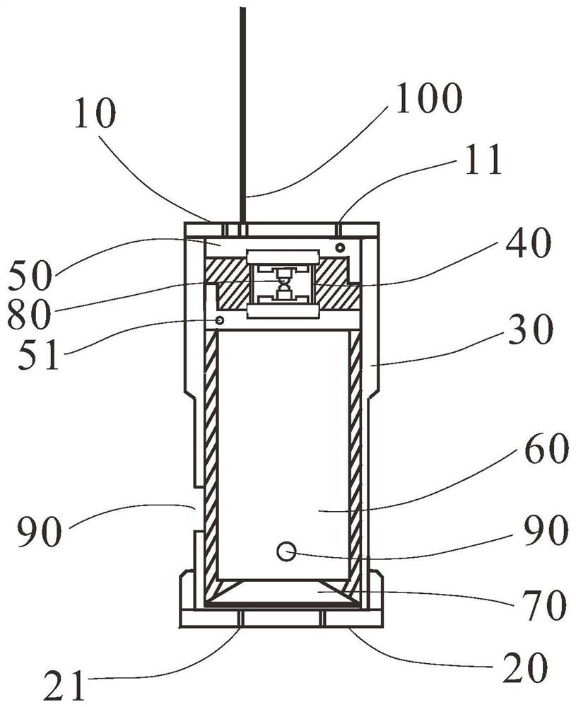
[0027] figure 1 It is a schematic structural diagram of a pressurizing device for a diamond chamber according to an embodiment. For ease of description, only parts related to the embodiments of the present invention are shown.

[0028] Such as figure 1 As shown, the diamond pressure chamber pressurization device includes a housing 30, an upper cover 10, a lower bottom 20, a diamond pressure chamber 40, piezoelectric ceramics 60 and piezoelectric ceramic lead holes 90; ...


PUM


Abstract

The invention is suitable for the technical field of diamond pressing cavities, and provides a diamond pressing cavity pressurizing device, which comprises a shell, an upper cover, a lower bottom, a diamond pressing cavity, piezoelectric ceramic and a piezoelectric ceramic lead hole, wherein the diamond pressing cavity and the piezoelectric ceramic are located between the upper cover and the lower bottom, the diamond pressing cavity is located above the piezoelectric ceramic, the piezoelectric ceramic lead hole is located in the side surface of the shell and supplies power to the piezoelectric ceramic lead, and dynamic control over pressurization of the diamond pressing cavity 40 is conducted by controlling the energizing current of the piezoelectric ceramic 60 so as to effectively ensure the pressurization continuity and controllability.

Description

technical field [0001] The invention belongs to the technical field of diamond pressure chambers, in particular to a diamond pressure chamber pressure device. Background technique [0002] The use of diamond pressure chamber technology to create a high-pressure environment and determine the physical and chemical properties of substances in extreme environments has been widely used in many fields including materials science and earth science. Traditional diamond pressure chambers use mechanical clamping devices (such as levers, bolts, etc.) to squeeze two diamond anvils that are facing each other, and generate pressure against the sample placed between them through their relative motion. [0003] However, this means of pressurization can usually only be adjusted by adjusting the tightness of the bolts, and after stopping at a certain "point", a static load related to the degree of tightness can be obtained. This mode of intermittent pressure application and pressure stop obs...

Claims


Application Information

Patent Timeline
IPC IPC(8): G01N3/02G01N3/18
CPCG01N3/02G01N3/18
Inventor 梅升华高悦赵霞孙建辉
Owner INST OF DEEP SEA SCI & ENG CHINESE ACADEMY OF SCI
Why Eureka
Try Eureka