
Laser communication coupling device and optical axis correction method based on same

A coupling device and laser communication technology, applied in the field of laser communication, can solve the problems of affecting the tracking accuracy, unable to meet the communication wavelength, unable to meet the simultaneous collimation function of the self-checking laser and the communication laser, etc.

Active Publication Date: 2022-01-14
上海遥目科技有限公司
View PDF4 Cites 0 Cited by
  • Summary
  • Abstract
  • Description
  • Claims
  • Application Information

AI Technical Summary

Problems solved by technology

The prior art CN201110071279.9 has the following defects: first, the optical fiber combiner described in this patent is only suitable for a specific short-wave band (800nm-900nm), and cannot meet the existing communication wavelengths around 1520nm-1580nm; second, The tracking camera cannot adapt to the multi-wavelength imaging function, and it is prone to defocusing, which affects the tracking accuracy; third, the aspheric collimation lens cannot meet the simultaneous collimation function of the self-inspection laser and the communication laser with a single wavelength; fourth, the system Real-time monitoring of the optical system of transmitting and receiving positions, and the ability to adjust the optical axis at any time

Method used


Image

  • Laser communication coupling device and optical axis correction method based on same
  • Laser communication coupling device and optical axis correction method based on same
  • Laser communication coupling device and optical axis correction method based on same

Examples


Embodiment Construction

[0233] The present disclosure will be further described in detail below with reference to the drawings and embodiments. It can be understood that the specific implementation manners described here are only used to explain relevant content, rather than to limit the present disclosure. It should also be noted that, for ease of description, only parts related to the present disclosure are shown in the drawings.

[0234] It should be noted that, in the case of no conflict, the implementation modes and the features in the implementation modes in the present disclosure can be combined with each other. The technical solutions of the present disclosure will be described in detail below with reference to the accompanying drawings and in combination with implementation manners.

[0235] Unless otherwise specified, the illustrated exemplary embodiments / embodiments are to be understood as exemplary features providing various details of some manner in which the technical idea of ​​the pre...


PUM


Abstract

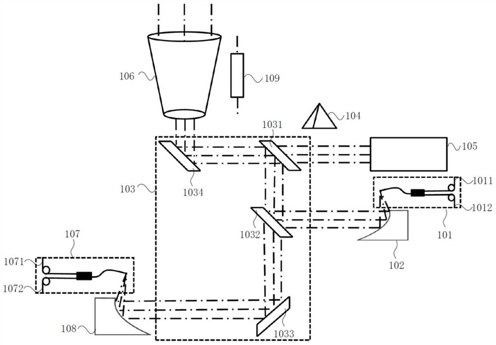
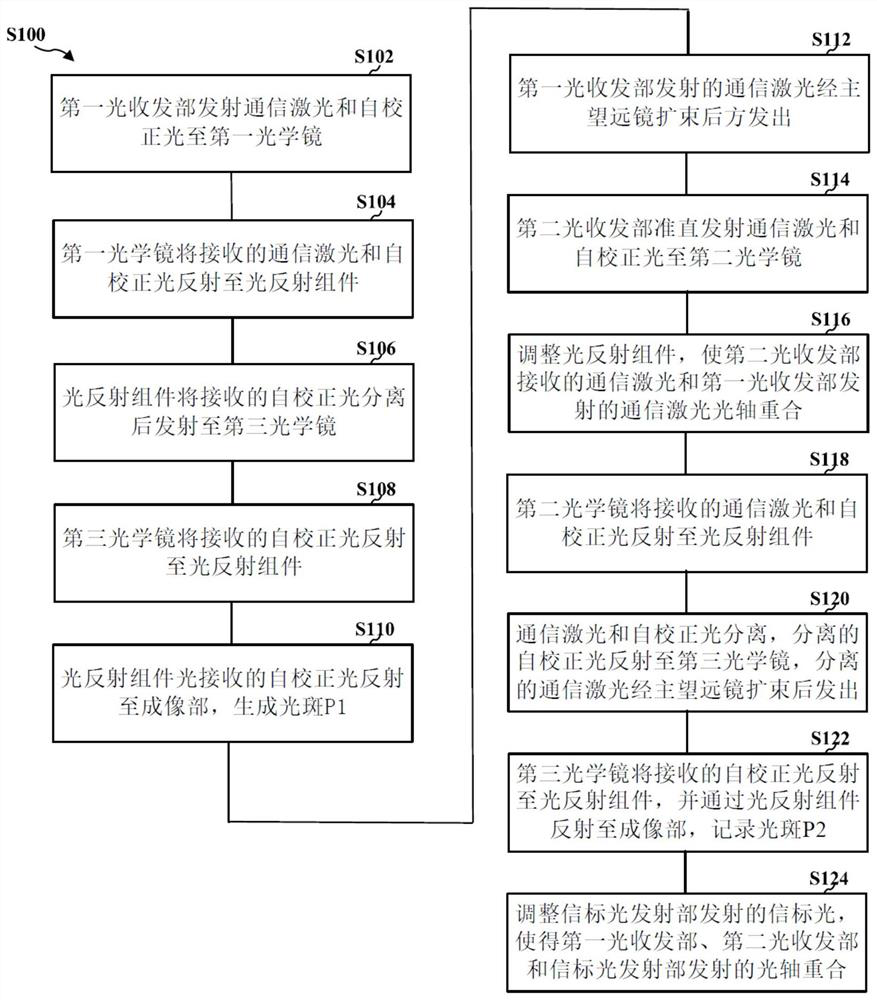
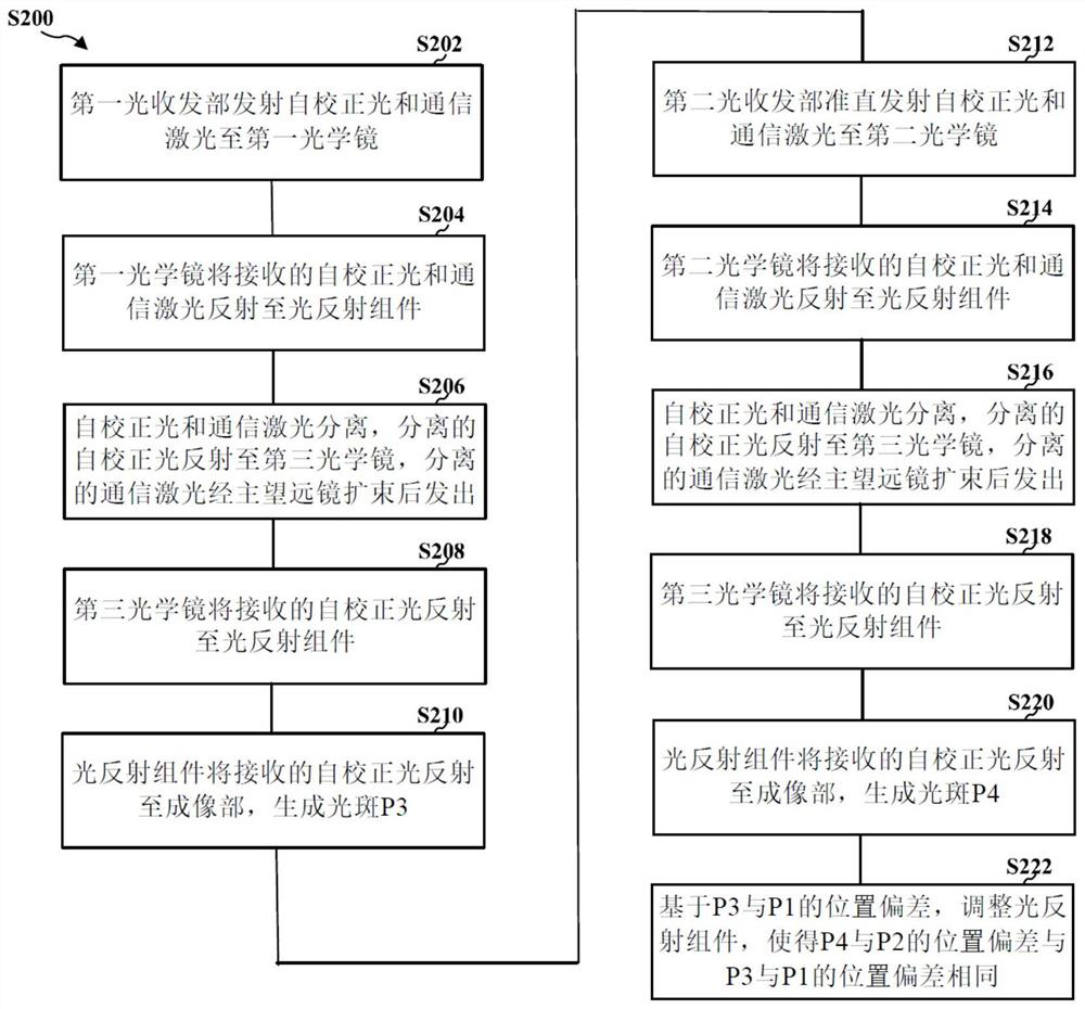
The invention provides a laser communication coupling device, which serves as a transmitting system to establish an optical axis. The laser communication coupling device comprises a first light transmitting and receiving part and a second light transmitting and receiving part which are used for transmitting self-correcting light and communication laser and receiving the communication laser; a first optical lens and a second optical lens which are used for collimating and transmitting the received communication laser to a light reflection assembly; the light reflection assembly which is used for transmitting and separating the received communication laser and the self-correcting light through reflection; a third optical lens which is used for collimating the received light; a main telescope which is used for expanding or shrinking the light passing through the main telescope; and a beacon light emission unit which emits beacon light. The laser communication coupling device can be used as a transmitting system to establish an optical axis and a correction optical axis, and can also be used as a receiving system to establish an optical axis and a correction optical axis. The invention further provides an optical axis correction method based on the laser communication coupling device. The laser communication coupling device can be used as a transmitting system, a receiving system and a transmitting and receiving system for optical axis correction.

Description

technical field [0001] The disclosure belongs to the technical field of laser communication, and in particular relates to a laser communication coupling device and an optical axis correction method based on the laser communication coupling device. Background technique [0002] The laser communication coupling device is an integrated device of an optical fiber collimation system and an optical beam expansion system. It is a receiving and coupling device for free-space laser communication using optical fibers, and mainly realizes the coupling and collection function of free-space light. [0003] With the development of laser communication, the advantages of laser communication are becoming more and more obvious. Among them, the laser emission beam is narrow, the directionality is good, the antenna size is small, the information capacity is large, the power consumption is small, the volume is small, and the weight is light. It is suitable for satellite communication, and Deep s...

Claims


Application Information

Patent Timeline
IPC IPC(8): G02B6/26G02B6/32G02B6/34
CPCG02B6/26G02B6/262G02B6/32G02B6/34
Inventor 王天洪吕世猛谢腾
Owner 上海遥目科技有限公司
Learn More