Electric tower grounding device

A technology for grounding devices and electrical towers, applied in the direction of connecting contact materials, etc., can solve the problems of not ensuring that lightning can be quickly guided to the ground, reducing the safety performance of the grounding device, and the failure of the grounding device, so as to ensure safe and stable operation, avoid failure, The effect of reducing ground resistance

Pending Publication Date: 2022-01-14
HUANENG TONGLIAO WIND POWER CO LTD
View PDF6 Cites 0 Cited by
  • Summary
  • Abstract
  • Description
  • Claims
  • Application Information

AI Technical Summary

Problems solved by technology

[0002] The electric tower introduces lightning into the ground through the grounding device to ensure the safe and stable operation of the power line. The grounding resistance of the existing grounding device of the electric tower is large, which cannot ensure that the lightning is quickly guided to the ground, and the grounding device is prone to failure, reducing the safety of the grounding device. Therefore, there is an urgent need to develop a grounding device for electric towers to solve the above problems and facilitate market promotion and application

Method used


Image

  • Electric tower grounding device
  • Electric tower grounding device
  • Electric tower grounding device

Examples


Embodiment Construction

[0020] The specific implementation manners of the present invention will be further described in detail below in conjunction with the accompanying drawings and embodiments. The following examples are used to illustrate the present invention, but are not intended to limit the scope of the present invention.

[0021] In describing the present invention, it should be understood that the terms "upper", "lower", "left", "right", "front", "rear", "top", "bottom" and the like are used herein to indicate The orientation or positional relationship is based on the orientation or positional relationship shown in the drawings, and is only for the convenience of describing the present invention and simplifying the description, rather than indicating or implying that the referred device or element must have a specific orientation or be configured in a specific orientation. and operation, and therefore should not be construed as limiting the invention.

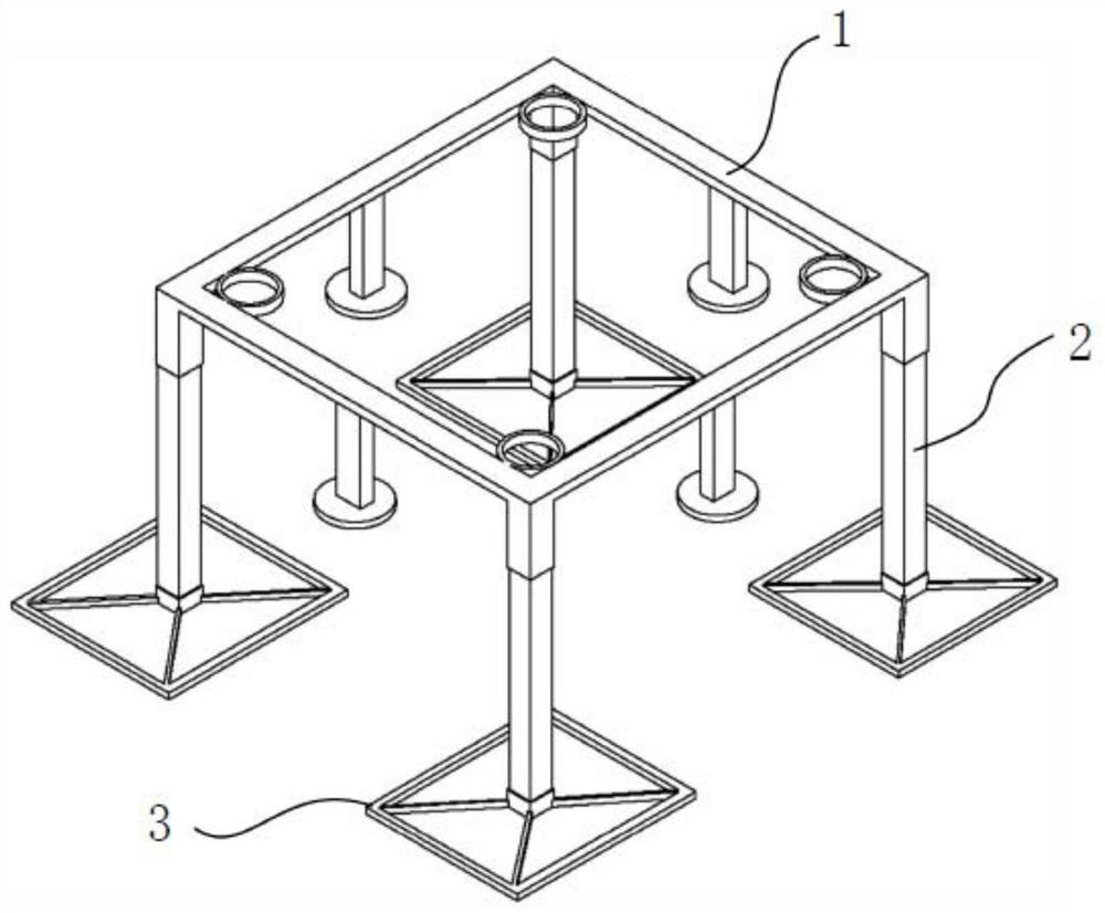
[0022] like figure 1 As shown, a gr...


PUM


Abstract

The invention relates to the technical field of electric tower grounding, and discloses an electric tower grounding device which comprises an upper grounding assembly, a grounding carbon rod and a lower grounding assembly. The upper grounding assembly comprises an upper grounding ring, a plurality of connecting rings and a plurality of first mounting sleeves, the connecting rings are welded to the inner side face of the upper grounding ring and located at the corners of the inner side face of the upper grounding ring, and the first mounting sleeves are fixed to the lower surface of the upper grounding ring; grounding carbon rods are in one-to-one correspondence with the first mounting sleeves, and the top ends of the grounding carbon rods are connected with the first mounting sleeves; and the lower grounding assemblies are in one-to-one correspondence with the grounding carbon rods, and the lower grounding assemblies are installed at the bottom ends of the grounding carbon rods. The upper grounding assembly guides thunder and lightning to the lower grounding assembly through the grounding carbon rod, the grounding resistance between the upper grounding assembly and the lower grounding assembly is reduced, and it is ensured that thunder and lightning current is rapidly led into the ground when thunder damage occurs.

Description

technical field [0001] The invention relates to the technical field of electric tower grounding, in particular to an electric tower grounding device. Background technique [0002] The electric tower introduces lightning into the ground through the grounding device to ensure the safe and stable operation of the power line. The grounding resistance of the existing grounding device of the electric tower is large, which cannot ensure that the lightning is quickly guided to the ground, and the grounding device is prone to failure, reducing the safety of the grounding device. Therefore, there is an urgent need to develop a grounding device for electric towers to solve the above problems, and to facilitate market promotion and application. Contents of the invention [0003] The technical problem to be solved by the invention is: the grounding resistance of the existing electric tower grounding device is relatively large. [0004] In order to solve the above technical problems, t...

Claims


Application Information

Patent Timeline
Patent Type & Authority Applications(China)
IPC IPC(8): H01R4/66
CPCH01R4/66
Inventor 李剑锋穆恩元赵朝古拉李金鹏李杨
Owner HUANENG TONGLIAO WIND POWER CO LTD
Why Eureka
Try Eureka