Optical module, receptacle equipped with isolator, and optical unit

An optical isolator, optical module technology, applied in optical components, instruments, optics, etc., can solve the problems of LD damage, wavelength deviation, variation, etc.

Pending Publication Date: 2022-01-14
KYOCERA CORP
View PDF2 Cites 0 Cited by
  • Summary
  • Abstract
  • Description
  • Claims
  • Application Information

AI Technical Summary

Problems solved by technology

It is known that whenever an LD is used, part of the light is reflected, and the LD is damaged due to the incidence of the reflected light, that is, the return light, on the act

Method used


Image

  • Optical module, receptacle equipped with isolator, and optical unit
  • Optical module, receptacle equipped with isolator, and optical unit
  • Optical module, receptacle equipped with isolator, and optical unit

Examples


Example Embodiment

[0016] The various embodiments are described in detail below with reference to the drawings.

[0017]

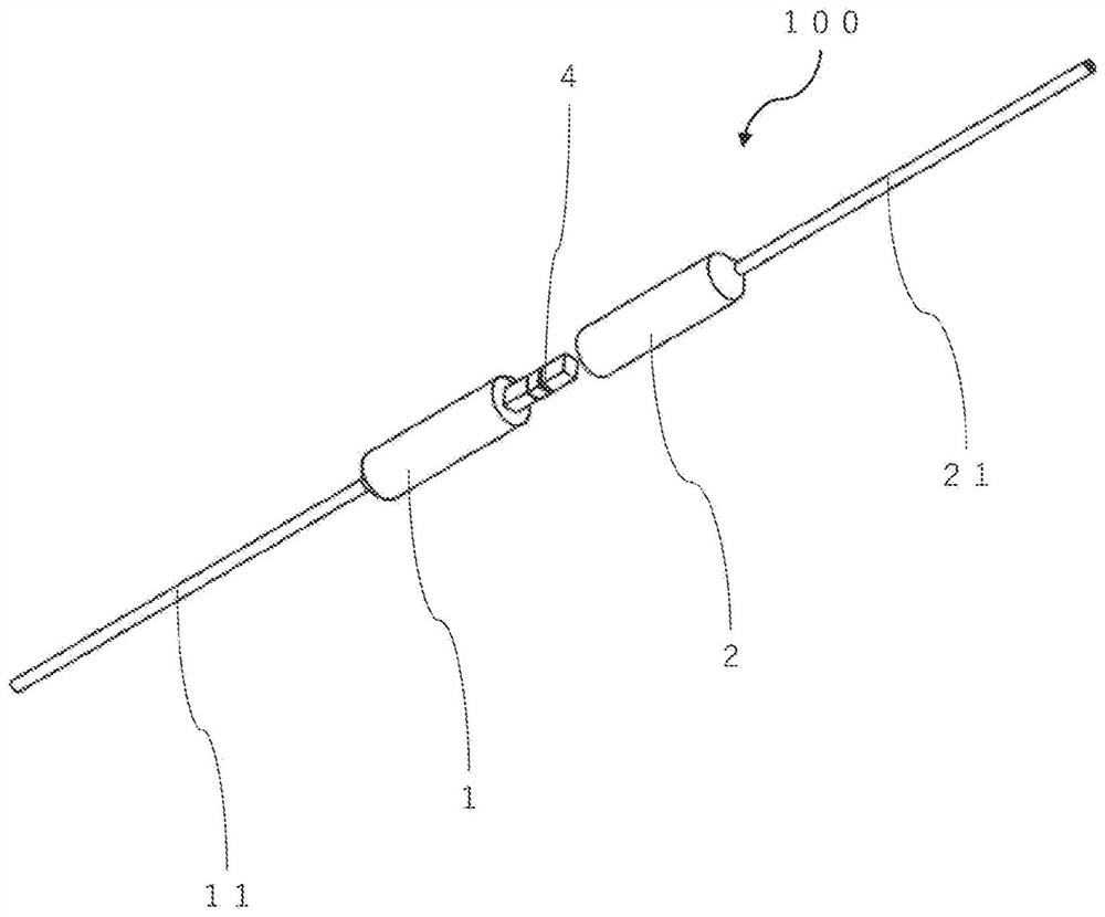
[0018] like figure 1 As shown, the present disclosure optical module 10 includes a first ferrule 1, a second ferrule 2, and a polarization-independent optical isolator 3.

[0019] The first ferrule 1 is, for example, a cylindrical shape or a cylinder shape. The first socket 1 is, for example, the size of the diameter is The length is 2.0mm ~ 10mm. exist figure 1 In the present, the optical fiber is shown in reference numerals 11, 12.

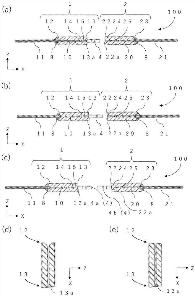
[0020] like figure 2 As shown, the first ferrule 1 includes a first end portion 12, a second end portion 13, and a first through hole 10 that penetrates the first end portion 12 and the second end portion 13. Here, the direction of the forward direction is figure 2 The light source in the X-axis direction, the light of the light source from the outside of the LD is incident on the opening of the first end portion 12, and is emitted from the open...


PUM


Abstract

An optical module according to the present invention is provided with: a first ferrule that has a first collimator lens; a second ferrule that has a second collimator lens; and a polarization independent opt-isolator disposed between the first and second ferrules. A receptacle equipped with an isolator according to the present invention is provided with the optical module, and a receptacle connected to the optical module. An optical unit according to the present invention is provided with the receptacle equipped with the isolator, and an external substrate connected to the receptacle equipped with the isolator.

Description

[0001] Cross-References to Associated Applications [0002] This application claims the priority of Japanese Patent Application No. 2019-100407 (filed on May 29, 2019), and the entire disclosure of this application is hereby incorporated by reference. technical field [0003] The present disclosure relates to an optical module, a socket with an isolator, and an optical module using a polarization-independent optical isolator having a function of reducing return light from the outside, which are used in optical communication and the like. Background technique [0004] Semiconductor lasers (hereinafter referred to as LDs) are utilized in optical communication systems, optical measurement systems, and the like. It is known that whenever the LD is used, part of the light is reflected, and the reflected light, that is, the return light enters the active layer of the LD to damage the LD. In addition, it is known that there are troubles such as wavelength deviation and fluctuation...

Claims


Application Information

Patent Timeline
IPC IPC(8): G02B6/27G02B6/32G02B6/42G02B27/28
CPCG02B6/3853G02B6/2746G02B6/3812G02B6/3829G02B6/3854G02B6/3885G02B27/30
Inventor 明石朋义庄田学史
Owner KYOCERA CORP
Why Eureka
Try Eureka